Ideas on a very small order + bypass switcher

We're thinking along the same lines, which is reassuring that I'm not way off track lol.

I plan on attaching the intact dust cover to the enclosure itself, not cutting them. I figured I would punch the center of each hole on the enclosure to use it as a template, but I didn't even realize I could do the same with the Orion enclosure...

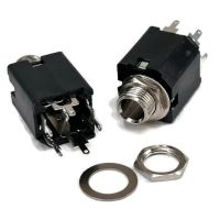
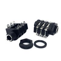
I like the idea of a switching jack, as well as hardwiring the Orions to on. I'm not sure how much I want to modify them yet, and it will depend on how easy they are to disassemble. I'm away, so I haven't been able to open them up yet.

Thanks again, this is super helpful stuff, and some great ideas!
 
Change of plans! I looked at the Orion guts, and it's a pair of PCBs connected via ribbon cable, so I don't think I'm going to rehouse them.

I plan on using this layout:
a-b-loop-switcher-order-switcher-only-master-off-by-mdc-png.89885


I'm going to use a 1590BBS, to make things easy on myself lol.

I'm also going to take your advice and use a relay for each switch, and add a remote jack for each.

A couple questions.
  1. How do I wire the remote jacks? My idea was to use a stereo jack, and connect the tip and ring to the same 2 connections as the SPST switch for the relay, then use a 1590LB with another stereo jack with the same lugs connected to another SPST switch. I am not sure which jack lugs I should use, and if I need to use the sleeve/ground lug at all. I have a Saturnworks Strymon favorite switch, which I think is doing the same thing, and I might be able to repurpose for this. It's got an LED though, which I won't need.
  2. I'd like to use this dual LED from LMS to indicate the A/B mode, and I'm not sure exactly how I'd wire them. From the diagram above, I think I'd just wire ground/cathode to the middle/ground lug of the A/B loop switch, and each anode to the the other lugs marked LED, but I'm not certain. And assuming I'm right, I'll be using the Basic Relay Bypass for each, so I'd have to figure out how to adapt the 3PDT to that.
  3. Regarding the relay, I've got 2 Basic Relay Bypasses built, so I don't need to buy anything else, like the DPDT one. I'm hoping that I can make it work with the bypass. I know I can for the master On/Off switch, and I'm assuming I can use it as an A/B, but I'm not certain. Any idea if I can, or I'll need to get the DPDT one? And would the LED work with either one? I'm having trouble visualizing how it would. Worst case I just use a 3PDT, and use remote switching for On/Off, which would be fine.
Thanks!!!
 
Pics or there's no Orions with multiple PCBs... 🤡


Now venturing into less-familiar-to-me waters, ie relays etc.
SO... take all the following with a chunky grain of pink Himalayan Salt...

1) JACKS
Use stereo switching jacks for your loops.
I want to say these: https://www.taydaelectronics.com/45015-dup-6-35mm-1-4-stereo-phone-jack.html
A-6982.jpg


However, for the remote-switch's jacks, you may probably need isolated jacks.
3617.jpg_1.jpg

You will need to use the ground lug as well, ie all — TIP RING SLEEVE — for the remote.


2) BI-COLOUR LED
You're good to go with the common cathode LED from BLMS.

SO, for the common-cathode bi-colour LED, yes you'd wire the cathode to ground, then wire the ANODES to the outer lugs and
+9V > CLR > common lug.

OR

If you've got too great a difference in brightness, give each colour its own CLR.
+9V > common lug > outer-lugs with separate CLRs > Anodes


BICOLOUR BYPASS-LED COMMON CATHODE.png


3) RELAYs
I'm pretty sure you can get it all to work, including the bi-colour LED, without resorting to mechanical switching — but I've never done it, so I haven't got any more clue than you how to do it — just have to work it out. Hopefully someone else has some knowledge... maybe @DGWVI or @szukalski or @BuddytheReow can help.


EDIT: there their now, just a typo, ol FF.
 
Last edited:
I always recommend common anode for things like this, and in general when able.
Better to switch the cathode(ground) as it avoids the off chance of shorting 9v to ground or to a signal wire at the switch or due to loose hardware etc. All of FFs recommended wiring schemes work the same, you're just inverting and adding a jumper to ground on that common lug and taking 9v straight to the LED. Individual CLRs between the cathodes and the switch.
Lowering the chance of sending 9-18 Volts to the IO or ground plane of an expensive digital device that has components operating at 3.3 or 5V seems like the way to go.
Even though I'm sure everything is decoupled and what not, better to be certain that it can't happen.
 
Pics or their's no Orions with multiple PCBs... 🤡


Now venturing into less-familiar-to-me waters, ie relays etc.
SO... take all the following with a chunky grain of pink Himalayan Salt...

1) JACKS
Use stereo switching jacks for your loops.
I want to say these: https://www.taydaelectronics.com/45015-dup-6-35mm-1-4-stereo-phone-jack.html
A-6982.jpg


However, for the remote-switch's jacks, you may probably need isolated jacks.
3617.jpg_1.jpg

You will need to use the ground lug as well, ie all — TIP RING SLEEVE — for the remote.


2) BI-COLOUR LED
You're good to go with the common cathode LED from BLMS.

SO, for the common-cathode bi-colour LED, yes you'd wire the cathode to ground, then wire the ANODES to the outer lugs and
+9V > CLR > common lug.

OR

If you've got too great a difference in brightness, give each colour its own CLR.
+9V > common lug > outer-lugs with separate CLRs > Anodes


View attachment 90870


3) RELAYs
I'm pretty sure you can get it all to work, including the bi-colour LED, without resorting to mechanical switching — but I've never done it, so I haven't got any more clue than you how to do it — just have to work it out. Hopefully someone else has some knowledge... maybe @DGWVI or @szukalski or @BuddytheReow can help.
Haha I will get some pics!

Mmmm, pink Himalayan is my favorite :)

Can you explain the purpose/advantage of the switching jacks for the loop jacks? I've not used them often, and I forget why I did. I have them in stock though. I think I get the isolated jacks for the remote switching though, and luckily I have them too.

I'm thinking I may start with a 3PDT for the A/B switch, which will enable the LED to work right off, and the relay for the master, which I also already know how to do. Then work up to getting the A/B relay going from a known good starting point.

Thanks again @Feral Feline, you're a gentlecat and a scholar.

And thanks @jwin615 ! I hadn't considered that about switching the common cathode. I only have common anode LEDs handy, but I may spring for some. Happy to have learned something new about them, as I never knew why/when to use which kind.
 
Yeah, I should've mentioned your recommendation, jwin615!

It was in the back of my mind from when you mentioned the reasoning of it in another thread, and I've taken it to heart for my own builds (luckily most of my own bi-colour LEDs are common-Anode — which is a little strange 'cause I remember when I started building pedals having trouble finding common anode—all I could seem to find was common cathode!
 
...

Can you explain the purpose/advantage of the switching jacks for the loop jacks? I've not used them often, and I forget why I did. I have them in stock though. I think I get the isolated jacks for the remote switching though, and luckily I have them too.

...

You really only need one (1) switching jack, at least for this build, but buying one-type jack in bulk might save you a few pennies in the long run.
Kind of like how some smaller commercial manufacturers get only 3PDTs for ALL their 3PDT and 2PDT needs — for 2PDT they just wire up the 3PDT and ignore one of the poles. Larger commercial builders have better economies of scale and can order the 2PDT switches in bulk and mount them directly to the PCB.

If you only buy stereo-switching jacks, you can use them for all your needs and you won't run out of a mono-switching jack 'cause you thought you still have some. If you run out of stereo-switching jacks, you know you're out completely, but you're not going to let that happen 'cause you'll see you're almost out of the one type of jack you have long before you actually run out. Anyway...


Connect the SEND SWITCH-TIP to the RETURN TIP (no need for switched jack on the return).

That way if nothing is plugged into the loop, the signal passes straight through. For example, you're on a gig and one of the delays goes down — just unplug it and signal will flow via the switched jack to the next delay. You can even use the OUT of the empty loop to send the signal somewhere else, the PA for example BUT there will be a volume drop because you'er passively splitting the signal sending it to the OUT.
Of course, there's no volume loss with the switched-jack loop if you have nothing at all plugged into the send/return jacks.

Ah ok, that makes sense! One switched jack for each loop send, and then I can unplug the delays and still have my signal pass through.

As promised:
orion-guts.jpeg
 
Wow!

And you say you've already traced it!

Amazing!


😜


It would take daze just to trace the audio path in that ! 🙀


Oh, and yes, one switched jack per loop.
Then you can experiment with having other pedals mixed in to the loops in place of or in addition to the delays.
Much more versatile, but eats up more real-estate than having just rehoused delays in a single box.
Choose your poison!
☠️
xxx
🍶
 
I have traced it already! But my girlfriend has the schematic. She goes to another school. In Canada.

Thanks again for all your help, once I get my enclosure in and the iron heated up, I'm sure I'll have more silly questions!
 
Making progress! Question on this part, do I also need to connect the non-switched SEND tip to the return tip? Seems like I would.

Nope.


Connect
SEND SWITCHED-TIP
to
RETURN TIP


OR
if your switched jack is the return jack
SEND TIP
to
RETURN SWITCHED-TIP


It is better to have the Switched Jack on the send, probably so you can use it as a passive splitter (two outs) if need be, ie:
IN, OUT and SEND have cables plugged into them, but not RETURN.


I'll see about sorting out a diagram when I'm back on my own computer.
Perfect, thanks! I am just doing a switched SEND currently, in case there's nothing plugged into that loop, per your suggestion earlier.
 
It's ALIVE!

And it all worked first try! Totally shocked. Good call on the switched SEND, works great even without anything plugged in, I had anticipated just having to leave it patched if there wasn't anything connected.

Pics attached for proof, and so I can be shamed for my rat's nest.

My last step is to add a remote switcher jack, which I should have done before wiring, but I wanted it working first. My plan is sleeve to GND, TIP to one pin of the relay, and RING to the other. think that'll work?

Thanks for all the help @Feral Feline, couldn't have done it without your help!
 

Attachments

  • switcher01.jpeg
    switcher01.jpeg
    366.7 KB · Views: 5
  • switcher02.jpeg
    switcher02.jpeg
    282.1 KB · Views: 5
Back
Top