Paragon Mini - No Sound

WrendorWC

New member
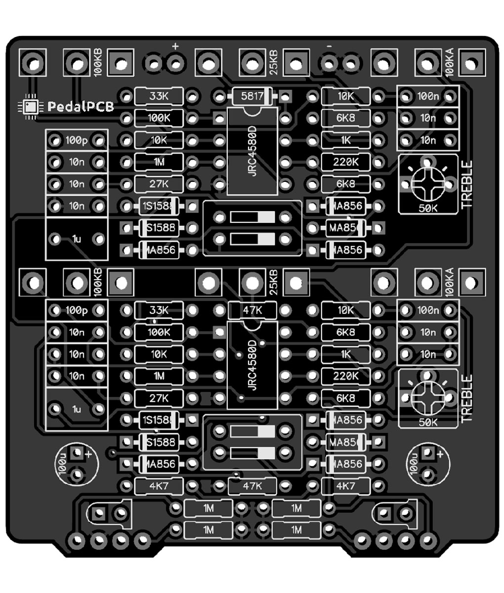
Looking for help troubleshooting my Paragon Mini build. I've looked for cold joints and reflowed a bunch of stuff, but right now neither side is working. I had the 1st (right / blue led) functioning for a minute but then it's gone quiet. Red doesn't work at all. LEDs work fine. Bypass works fine. IC Voltages are approximates (and weirdly on the bottom IC pins 1 and 2 start high (like 3.5v) and then slowly drop to what I've shown below). BD646DAA-CB87-4CE7-8432-E6FF5B81FF90.jpeg B18A76F3-4255-4EFD-8A28-AC222060E91C.jpeg
4810BB80-B3C2-4AA0-8595-7F855B41E426.jpeg 7FAE0F49-BD3B-4C2B-A4B1-9F8DF9259283.jpeg
Top IC voltages:
1: 4.5
2: 4.5
3: 4.5
4: 0
5: 4.5
6: 4.5
7: 4.5
8: 8.5v (that's what this power supply puts out)

Bottom IC voltages:
1: 1.6
2: 2.6
3: 4.5
4: 0
5: 4.5
6: 45.
7: 4.5
8: 8.5v

Thank you!

EDIT / UPDATE 6/21/2025: The first stage is working now. I think it was just a wiring issue between the switch and the board that has now been corrected. I've been trying to troubleshoot the bottom stage (2) and have found that something is weird at the op amp. The audio is coming into pin 3, but NOT leaving pin 1 (which has that lower than expected voltage - 1.6 vs 4.5). I swapped the two op amp chips to see if that made a difference but it does not. So now I'm just scratching my head because I have no idea what's wrong. Anyone have any suggestions or next steps?
 
Last edited:
I once had a ribbon cable like that fail on me, there was a break in the wire inside. It’s a long shot, but maybe worth checking for continuity on both ends. Is the red LED still not working?

Are you using an audio probe to trace the audio through, is that how you know it is stopping at the op amp?
Yes I ended up replacing both ribbons from the switches to the main pcb with wires. Lots of fun desoldering!

Both leds are working now. The issue is just with the 2nd side audio. I've been using a probe to diagnose it. I don't understand enough about the function of the op amp to understand what could be causing the low voltage on pin 1.
 
Gotta (probably) be somewhere between pin2 and ground. Look at schematic. Probe voltages on good side, compare to bad side.
Example: junction between pin2 and R22. Also junction between R22 and C17. Etc.
I checked a lot of those resistors and they look right. Might be a bad solder joint on one of those caps.
 
Well that's a nightmare. I'll compare stripes to the other (working) side and see if I see anything weird.

That would help, but...

I would look at each resistor's stripes and enter them into Digikey's resistor calculator (make sure you're in 5-band mode!);
compare the Digikey results to the board image AND the schematic — that's what I'd do since measuring in circuit doesn't work — unless you want to remove, measure, and reinstall every resistor...

MAKE PARTICULAR NOTE of resistors that can easily be misconstrued for another value when reading back-to-front such as:

brown red black black brown = 120Ω;​
brown black black red brown = 10k.​

or

brown orange black black brown = 130Ω​
brown black black orange brown = 100k​

etc.
ParagonMini.jpg
How would I be able to tell if I had mixed up the orientation of a resistor (meaning I had the stripes backwards and it was a totally different value) unless I remove them from the circuit and test them?
 
How would I be able to tell if I had mixed up the orientation of a resistor (meaning I had the stripes backwards and it was a totally different value) unless I remove them from the circuit and test them?


For most resistors, you'll be able to tell if it's the correct value or not simply because reversing the colour bands gives a non-sensical value — for example:

yellow purple black red brown = 47k​
brown red black purple gold = 1.2 Giga Ohms​

Note the last band above is "gold" ... cause there isn't a yellow tolerance-band, but the 1.2 Giga Ohm resistor (as per Digikey's calc) is a dead giveaway that it's not the correct value. There may exist such a resistor, but ...
A) you likely didn't order any, even by accident;
B) Tayda doesn't carry that value.


How about this:

red red black red brown = 22k​
brown red black red red = 12k​

If you've bought only one type of resistor, all 1%-tolerance metal-film resistors,
then the last band of the 12k above being 2% would be known to be incorrect.
Tayda, as an example again, doesn't carry 2% resistors; while mouser does carry 12k resistors at 2%, they cost more than $4 each, so again unlikely you bought any of those by mistake.

One last example:

brown blue black red brown = 16k​
brown red black blue brown = 120M​

Unlikely you've bought 120MΩ resistors, neither Tayda nor Mouser sell such a thing, at least none that I could find.

Red can sometimes be mistaken for brown; a few other colours can be off, too, such as purple and blue.
If you bought all 1% resistors, that means the last band should be brown, so you only need to MAYBE remove and check a few resistors that you've bought.

Mostly you can rely on reading the colour bands and deductive reasoning.


PS: NB! SUGGEST when building, measure each resistor with your DMM before you populate it — this will save you many headaches of troubleshooting by finding incorrect value that got mixed up in your parts stash or a faulty component right from the manufacturer...

Also suggesting: When populating, orient the resistors all the same way so they read from left to right and bottom to top (or whatever you want, just be consistent) — this also aids trouble-shooting when problems arise.
 
Last edited:
Pin 1 and pin 2 of both ICs should be the same, and should be sitting at 4.5V. It should be biased at that voltage by the 1M resistor on pin3. Pin 3 is the correct voltage, so I wold be looking for an incorrect component value or a short around the feedback network (R30, C13/16/17, drive pot, etc). As you have a working side, I would probably take some voltage and resistance etc measurements on both parts and see if there are differences.
 
Back
Top