
You are using an out of date browser. It may not display this or other websites correctly.
You should upgrade or use an alternative browser.
You should upgrade or use an alternative browser.
Rotary chorus
- Thread starter jimilee
- Start date
jimilee
Well-known member
Exactly.like the old ibanez rc99? good question because that would be a pretty good project
ICTRock
Well-known member

MANGEL WURZEL
Clone board set of the Ibanez RC-99 Rotary Chorus. This chorus is unique in that it provides a certain warble that we have not found in any other...
 www.deadendfx.com
jimilee
Well-known member
Very cool, thanks.I didn't know they made one but that's where I started my search because if it's something niche I'd be into, they usually have itMANGEL WURZEL
Clone board set of the Ibanez RC-99 Rotary Chorus. This chorus is unique in that it provides a certain warble that we have not found in any other...
ICTRock
Well-known member
Same … and rotary for that mattermust...resist...already...have...chorus'...out...the...ass...
Audandash
Well-known member
So i haven’t built this yet but I do have it. I was doing some measuring yesterday for the box and also trying to source some of the parts. Its kinda wonky. I think i found some spacers from tayda that will work but i am not 100% yet. I will post info once I get a little deeper into it and share my template if it works. This is my first deadendfx project. I have eye balled a few for a while but finally pulled the trigger on this one. Some of them have ferrite beads listed in their bom’s and I have never been able to find a source for them. They have a few interesting projects i haven't seen anywhere else. This is one of them.
jimilee
Well-known member
I know tada has / had them. I’m not sure about @StompBoxPartsSo i haven’t built this yet but I do have it. I was doing some measuring yesterday for the box and also trying to source some of the parts. Its kinda wonky. I think i found some spacers from tayda that will work but i am not 100% yet. I will post info once I get a little deeper into it and share my template if it works. This is my first deadendfx project. I have eye balled a few for a while but finally pulled the trigger on this one. Some of them have ferrite beads listed in their bom’s and I have never been able to find a source for them. They have a few interesting projects i haven't seen anywhere else. This is one of them.
Audandash
Well-known member
The ones i have seen at tayda don't match the specs they have listed in the bom. No worries though, it’s not this project ") . I don’t know much about them to be honest. The best I can tell looking at the schematics is its acting as some sort of power filter. It looks like they are adding those like folks add the 100n cap at the power. Anyway Tayda does have the bc547b and Lm833 that seems to be a good alternative for the upc4570. It has very similar specs and slew rate. The only thing i couldn't find at tayda was lm78L08. (Obviously not the 571, 3207 and 3102)
. I don’t know much about them to be honest. The best I can tell looking at the schematics is its acting as some sort of power filter. It looks like they are adding those like folks add the 100n cap at the power. Anyway Tayda does have the bc547b and Lm833 that seems to be a good alternative for the upc4570. It has very similar specs and slew rate. The only thing i couldn't find at tayda was lm78L08. (Obviously not the 571, 3207 and 3102)
. I don’t know much about them to be honest. The best I can tell looking at the schematics is its acting as some sort of power filter. It looks like they are adding those like folks add the 100n cap at the power. Anyway Tayda does have the bc547b and Lm833 that seems to be a good alternative for the upc4570. It has very similar specs and slew rate. The only thing i couldn't find at tayda was lm78L08. (Obviously not the 571, 3207 and 3102)jimilee
Well-known member
Wow, a 3 volt regulator? That’s a new one.The ones i have seen at tayda don't match the specs they have listed in the bom. No worries though, it’s not this project
Had one as well, been well over 10yrs.
My one and only complaint was that the rate came on too fast too quickly. Never considered modding the one I had, but looking at the DEFX parts list, might be worth trying a 25K-A rate pot (vs the stock 50K-A).
And yes. Crap. I didn't need to know this was out there, because it DOES sound really good when you drop that rate down.
falco_femoralis
Well-known member
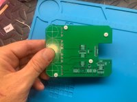
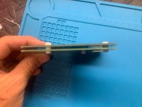
I purchased one of these as well and it arrived yesterday. I was getting into it - I think I'm going to eschew the 3mm spacers and use a thin sheet of plastic to insulate the two halves - like what Boss does to insulate their boards from the back panel. That along with well trimmed solder leads should bring the gap down to 1mm instead of 3.
Also, using Lumberg open style jacks which are 14.5mm across instead of 19mm switchcraft style pictured in the build doc means I should be able to get it in a 1590bb2 enclosure rather than a bbs, which is 38mm tall rather than 42. I would have liked to get it into a regular bb, which is 34mm in height, but there just isn't going to be any room. If I chose to not use sockets for the chips I could have gotten it down even further, but I don't want to deal with unsoldering a chip should a problem arise. I'm still going to try for the bb but it's doubtful.
Also, in the build doc they are using pan head screws to mount the two boards together, which you can clearly see are pushing up against one of the pots, adding to the clearance issues.. Leaving some of these screws out will alleviate the clearance problem further.
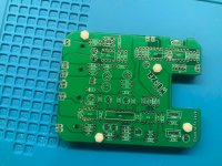
It would have been nice if they'd designed the boards differently. There is a lot of empty space on both boards and I can't help but think it could have been consolidated into one. The build doc mentions the boards were designed this way to mimic the original design, which I don't believe is necessary.
In classic style this uses a lot of resistor values I don't have, like 24k, 75k, and 300k, and I just placed orders from three separate parts companies.
Also, using Lumberg open style jacks which are 14.5mm across instead of 19mm switchcraft style pictured in the build doc means I should be able to get it in a 1590bb2 enclosure rather than a bbs, which is 38mm tall rather than 42. I would have liked to get it into a regular bb, which is 34mm in height, but there just isn't going to be any room. If I chose to not use sockets for the chips I could have gotten it down even further, but I don't want to deal with unsoldering a chip should a problem arise. I'm still going to try for the bb but it's doubtful.
Also, in the build doc they are using pan head screws to mount the two boards together, which you can clearly see are pushing up against one of the pots, adding to the clearance issues.. Leaving some of these screws out will alleviate the clearance problem further.
It would have been nice if they'd designed the boards differently. There is a lot of empty space on both boards and I can't help but think it could have been consolidated into one. The build doc mentions the boards were designed this way to mimic the original design, which I don't believe is necessary.
In classic style this uses a lot of resistor values I don't have, like 24k, 75k, and 300k, and I just placed orders from three separate parts companies.
Audandash
Well-known member
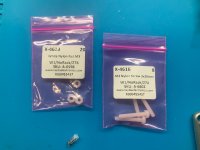
Update on my prep for this. I found some nylon nuts and screws on tayda for this. They are 2mm instead of 3 and seem to work great on my dry fit. The screws are way too long but once they are attached i just snipped them off since its nylon. Here are the part numbers as well.
Attachments
Last edited:
Audandash
Well-known member
Use at your own risk. I “think” this will work but it is not confirmed. The top jacks are from a madbean project and Bean gets them as close as they can be to the edge. The pots i took measurements off the board myself. I am going to order one and I will verify but if you want to try before me have at it.
falco_femoralis
Well-known member
I found a type of thinline 1/4 jacks on tayda that are a scant 11mm across. I'm going to order these along with the Lumbergs and see what I can make work. I'm probably a month out from finishing this due to the number of parts I have to order for it, and then paint
Feral Feline
Well-known member
All this time I've been looking for a "Rotary Choeus"...
jimilee
Well-known member
Gotcha!All this time I've been looking for a "Rotary Choeus"...

Similar threads
- Replies
- 12
- Views
- 570
- Replies
- 46
- Views
- 3K
- Replies
- 2
- Views
- 339