Notakliche (Ghostbusters Edition) - First Build

SwiftReason

New member
Build Rating
5.00 star(s)
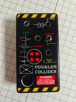
I have the JHS Notaklon and its great but a little too big. So i decided to build the Notaklichè since it goes in a smaller enclosure. I also wanted to do a fun design. I chose Ghostbusters. It's my first time designing an enclosure and my first time building a pedal. I definitely learned a lot. I was short 3 capacitors so once those come in and I solder them on i'll be able to test the pedal to see if it works.

1760573803343.png
1760573830305.png
1760573855092.png
 

Attachments

  • 1760573761125.png
    1760573761125.png
    788.7 KB · Views: 23
But hey, no worries! Happy first build! I actually did this same thing on my first build. I even started a thread on what to do with it and it has answers:

 
I really like your enclosure design - very cool, even if I didn't get the Ghostbusters references (having never seen the movie). Just as well you didn't do a Back To The Future theme. Flux capacitors are hugely expensive because of tariffs.
 
But hey, no worries! Happy first build! I actually did this same thing on my first build. I even started a thread on what to do with it and it has answers:

Depends on where the other wires go.
 
I really like your enclosure design - very cool, even if I didn't get the Ghostbusters references (having never seen the movie). Just as well you didn't do a Back To The Future theme. Flux capacitors are hugely expensive because of tariffs.
Thanks! I actually would like to do a BTF themed pedal as well.
 
But hey, no worries! Happy first build! I actually did this same thing on my first build. I even started a thread on what to do with it and it has answers:

Im going to attempt desoldering and resoldering since the pcb part came with the kit. Not sure if i could even buy it separately.
 
Im going to attempt desoldering and resoldering since the pcb part came with the kit. Not sure if i could even buy it separately.

I would heed jcpst's advice in post #6.


Desolder or clip the wires and put some shrink-tube on the wire, resolder the wires mirrored and slide the heat-shrink tube over the newly soldered clipped wires.

Better to have some wires crossing each other than to toast a footswitch trying to remove the daughterboard — especially if you've never desoldered anything before.

Even if you're an old solder-hand and just new to pedals, desoldering a 3PDT-switch's daughterboard is a bitch and you'll more than likely have a non-functioning footswitch at the end of the effort.


I'm not saying it can't be done, just that it's difficult and the chance of success is much smaller than successfully simply re-wiring the existing backwards-daughterboard to the main-PCB.


From jcpst's thread:

3pdt-daughterboard-wiring-diagram-pedalpcb-flipped-png.74017
That makes sense. Thank you for the detailed explanation. It seems reversing the wires will be the easiest.
 
Another way of thinking of it is to wire what you have now “upside down”. So that the footswitch is pointing the wrong way. Then the wiring is correct and you twist it 180 to orient the footswitch correctly. If that makes sense.
It does make sense. Thank you for the advice!
 
Back
Top