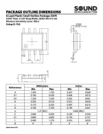
A new-production BBD, with added features!

And power supply voltage is only 5V according to the datasheet. Not much of a headroom for the guitar signal.
Optimal Input Signal Range: 40..440mV.
512-stages is interesting though.
 
The S/N spec is pretty underwhelming for such a short delay. Gets even worse if daisy chaining a few
Was kinda taken back by that as well. I'd be curious what the spectrum looks like and if it's impacted by lower clock freq.
And power supply voltage is only 5V according to the datasheet. Not much of a headroom for the guitar signal.
Optimal Input Signal Range: 40..440mV.
512-stages is interesting though.
I think both the noise and 5v could be better fixed via compander/expander or pre emphasis/de-emphasis
 
So who’s trying one of these out?!? Would they work in existing circuits or do we have to make a new one?
I've pre-ordered a few of them from CabinTech Global to try out. After reviewing the datasheet and comparing to other 8-pin DIP BBDs, they are not pin-for-pin compatible. So a new layout would be needed. Considering the SSI2100's power requirements, I do see that it might be possible to create an MN3207 conversion/adapter PCB for swapping in an SSI2100. I haven't fully explored that route yet.

Once the pre-ordered SSI2100s arrive, I'll get one on a breadboard, see what I can come up with and post back.
 
And power supply voltage is only 5V according to the datasheet. Not much of a headroom for the guitar signal.
Optimal Input Signal Range: 40..440mV.
512-stages is interesting though.

According to the linked web-page, Guitar Bomb, the 5v is just for the clock...


Note the text I circled in magenta; Legitimate Question: Am I missing something above?


Sound-Semiconductor-SS12100 datasheet.webp
 
If it has a built-in clock, why does it have a Clock pin (pin #8)?
I was trying to to figure this out, too - I think what it means is that in the "classic" BBDs there are two separate clock pins
that step back and forth, leading to potentially more complicated offboard circuitry, where this chip just has a single clock
pin that expects a square wave input. Ultimately the point of the device is to dynamically vary the delay and the only way to do
that is by changing the clock. (Though I guess they could do some kind of voltage controlled oscillator input directly)
It looks like there's no getting away from some kind of external clock driver, though hopefully it's much simpler than the
V3102 and/or CD4047 to drive the clock. (e.g. Maybe we could get away with a simple 555 timer, etc)
 
According to the linked web-page, Guitar Bomb, the 5v is just for the clock...
Note the text I circled in magenta; Legitimate Question: Am I missing something above?
Good question. I guess internally generated Vgg doesn't automatically cancel this requirement from the datasheet:
ABSOLUTE MAXIMUM RATINGS, Maximum Voltage into Pins - 7V. But I might be wrong.
 
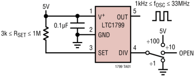
I think the LTC1799 would be a suitable clock. It, a pot, 1 cap and 1 resistor is all it would take to have variable clock.
From the SoundSemi datasheet

The clock input (pin 8) is compatible with TTL and CMOS logic levels in both 5V and 3.3V systems. It should be driven by a square wave with equal high and
low periods and fast transitions. If your design cannot guarantee this requirement then we recommend using a flip-flop to ensure a clean square wave, and
then to double the frequency range of the clock source to compensate.
The clock frequency range of the SSI2100 is very wide, and will perform within specifications from 1 kHz to over 2MHz. It can be clocked both lower and
higher with some degradation in performance. As the SSI2100 is a sample-based device its behavior is subject to Nyquist limits, where the clock signal
needs to be at least twice the highest signal present in the input signal
 
Last edited:
Note, the 1799 goes from 1kHz to 33MHz, hence the one resistor(in series with the pot as a variable resistor between pins 1 and 3)
1000000340.png
Edit: oops, completely ignored the DIV pin
Probably still need a resistor though.
 
Back
Top