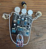
Triad Compressor: VREF Too High?

gorpo

New member
Hello,

I built the Triad Compressor a while ago, and I feel like it worked at first (maybe not). But now it just sounds like a bad fuzz sometimes and only outputs sound with the sustain maxed out. I was doing some testing, and I found that the junction between R100 and R101 (which supplies VREF) was measuring ~6.5V instead of ~2.5V. This would seem to imply that the resistors are in the wrong spots, but I've triple checked that the right values are in the right positions.

Is there anything else that could be affecting the value of VREF? I did have the electrolytic capacitor C2 installed with the wrong polarity. That has since been fixed, but could that have taken out another component when it was wrong?

Link to build doc

PXL_20251101_185257231~2.jpg
 
Last edited:
Solution
Final Update: I re-flowed all the solder, but it didn't make a difference. I confirmed every component value through visual inspection, and everything checked out. I started removing suspected faulty active components until they were all gone, removed electrolytic caps, and basically everything not in the voltage divider part of the circuit.

Finally decided to check the 22k resistor in the voltage divider... It read open. The board is pretty much toast, but I feel satisfied having found the source the of the problem. The funny thing is that the checked the other resistor in the voltage divider early on and never thought to check the one that ended up being the problem.
Update: I've confirmed values of all components as well as all off-board wiring. I have a few backup CA3080AEs, so I swapped in one of those to no avail. I used the diode mode on my meter to test the diodes and the transistors (on the board, no idea if this is a good indicator). I'm going to try re-flowing all of the solder at this point.

Here are the voltages for the pins on the IC
1 - < 1 mV
2 - 4.3 V
3 - 4.3 V
4 - 0 V
5 - 0.7 V
6 - 5.22 V (This value is high compared to values from a Dynacomp or Ross.)
7 - 9.14 V
8 - < 1 mV
 
Just looking at the top of the board, your soldering could use some help. I can see through the solder pad on a lot of the components. Go back and reflow the solder through the board and see where that gets you.
 
Final Update: I re-flowed all the solder, but it didn't make a difference. I confirmed every component value through visual inspection, and everything checked out. I started removing suspected faulty active components until they were all gone, removed electrolytic caps, and basically everything not in the voltage divider part of the circuit.

Finally decided to check the 22k resistor in the voltage divider... It read open. The board is pretty much toast, but I feel satisfied having found the source the of the problem. The funny thing is that the checked the other resistor in the voltage divider early on and never thought to check the one that ended up being the problem.
 
Solution
This tells me that I'm doing the right thing by testing every single resistor before installing it. It doesn't take long and it's partly to make sure I have the right value, ie I'm using a 10K rather than a 1K, but also to make sure the resistor is correct. And I have never found a metal film resistor which is not within tight tolerances in over 100 or so pedal builds. But there is always that one time I guess!
 
Back
Top