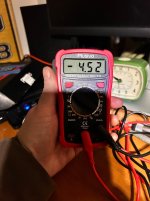
I just completed my first build and I am having an issue when testing the final product. I built a Silimile Fuzz Face clone, when the pedal is off I have a signal that passes through with no issues. When I engage the pedal I need to have the volume and fuzz knobs all the way up to get anything that I can hear on the amp. I used the sockets provided for the transistors but can’t seem to get them to fit in without them moving around a lot. I was originally getting a reading when I biased the circuit to 4.5, but now I am getting weird readings not even close. I have 2 germanium transistors on the way, my thinking (hoping) is that if I actually solder the new transistors in it may solve my problem?
You are using an out of date browser. It may not display this or other websites correctly.
You should upgrade or use an alternative browser.
You should upgrade or use an alternative browser.
Silismile Fuzz problem (low volume/fuzz output)
- Thread starter Drlufk00
- Start date
I installed the NPN silicone transistors that came with the kit. I was planning on swapping the out for some lower HFE germanium ones. Is that not possible?pictures of your build? Your aware the silismile is NPN transistors correct?
swelchy
Well-known member
It's not impossible but pretty hard to find NPN germaniums.... My guess is you have your pinout for transistor legs installed wrong.. but honestly for us to help identify what other things you might have going is to read the sticky and post good pics of your build so we can catch whats going on.I installed the NPN silicone transistors that came with the kit. I was planning on swapping the out for some lower HFE germanium ones. Is that not possible?
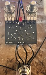
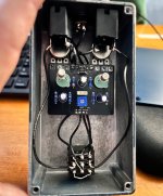
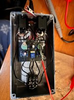
Pics of the board… I know the solder work could use some improvement. I am wondering if I did get the socket for Q1 as far in as I should have?
Attachments
swelchy
Well-known member
no.. it's a little more complicated than that... pnp uses positive ground.. you would have to flip polarity on a few thingsI understand that if I order PNP transistors they have a different pinout and I would need to cross the legs
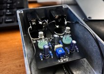
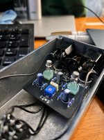
What I can see is a possible short on your diagonal wire on the stomp switch.. and from the angle it almost looks like a potential bridge on your electrolytic cap in center of pcb.. Also your trimmer pot seems to be centered/untouched.... there is a sweet spot on that trimmer that needs to be in just the right spot for the pedal to work properly..... you can set the bias with a multimeter but I generally adjust the pot on this particular build by ear.... it is a narrow range...
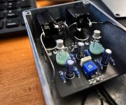
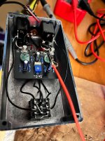
Definitely no short on the dpdt switch… just a bad camera angle. I uploaded another one that shows it better. I can even adjust the bias using a multimeter… I don’t get a good reading. I think it’s a transistor problem. I order some npn germanium transistors. LED lights comes one, I don’t think it’s a power issue.
Attachments
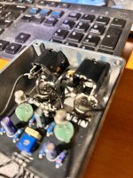
BC108What transistors came with your kit?
2222s? BC1xx? Can't see in the photos
K. Pinout is correct. Is that plumbing solder? That's really large gauge for electronics work
I would reflow all your joints. There's a lot that aren't great. Solder should flow through the through hole at least flush to the other side of the PCB. you have some pads that are even full on the solder side.
Low/weak signal in a transistor fuzz is usually only a few things
Practice will prevail with soldering
Shooting for a fillet like this on the right.

Also, don't put Ge in here. There are more skills to acquire before one can just throw Ge at a fuzz designed for silicon transistors. You'll get there and we'll help but let's fix what you got here first
I would reflow all your joints. There's a lot that aren't great. Solder should flow through the through hole at least flush to the other side of the PCB. you have some pads that are even full on the solder side.
Low/weak signal in a transistor fuzz is usually only a few things
- Transistor pinout incorrect
- Short/solder bridge/cabling issue
- Improperly biased transistors
- Bad/cold solder joints
Practice will prevail with soldering
Shooting for a fillet like this on the right.

Also, don't put Ge in here. There are more skills to acquire before one can just throw Ge at a fuzz designed for silicon transistors. You'll get there and we'll help but let's fix what you got here first
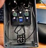
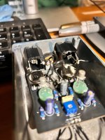
Was able to bias the transitory after deciding to solder the legs onto the socket. Got it very close to 4.5. Signal passes through no problem when the pedal is off. When I switch it on I don’t get any real hum and I have to turn both volume and fuzz to about 4 o’clock to get a loud enough sound. I can get what I want out of it this way, so I may just consider it a win.
Attachments

Still curious as to why if I matched polarity with a germanium transistor to the polarity of the silicon transistor a swap won’t work? I am not an electrical expert so I just want to know what I am missing. Was actually wanting to do a hybrid pedal… hypothetically if one where to do that, would you put the germanium in Q1 or Q2?
swelchy
Well-known member
If they are NPN germaniums it would work... Maybe...But... a few things come into play. Be mindful of the pinout of transistors that you want to pop in...The HFE/Gain of the transistor and it's leakage come into play..... R3 resistor and the trim pot may need to be adjusted to different values to be able to get the germaniums into the correct bias range so the pedal can bias correctly.. that all depends on the gain and leakage of the germaniums you get.... In other words... sure try it... But I bet most of us would suggest you breadboard the circuit first with the same values and your transistors to check if it all works out before just whacking it on a pcb...Still curious as to why if I matched polarity with a germanium transistor to the polarity of the silicon transistor a swap won’t work? I am not an electrical expert so I just want to know what I am missing. Was actually wanting to do a hybrid pedal… hypothetically if one where to do that, would you put the germanium in Q1 or Q2?