OD is Glorious
Well-known member
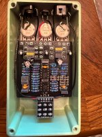
This pedal went together easily and I enjoyed the process. I am working my way through the PedalPCB offerings. Pretty wild to have four toggle switches on an overdrive! I am trying to enjoy this journey rather than rushing to complete pedals. I enjoyed this build, I did not enjoy that you need hard(er) to find Zener diodes, two odd-size film capacitors and two 13k resistors. You can see I ran two resistors in series to get to 13k (12k and 1k). I also used two film caps that were slightly higher than the build called for. FYI… that 470u EC is a rotund cylinder which barely fits.The 220u is also quite a fatty. Using ECs I am trying to keep to 25v and 16v at the lowest. It was a clean no problems build and it worked as soon as it got onto the PedalPCB Platform. I boxed it and put it through testing.
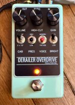
I see one Derailer user made a Youtube video and compared this to a Dumble. It does have a good selection of sounds. Mine is clipping with Zenner 2.0s because I have not ordered the 1v8s. I have all diodes socketed for swapping. I think to get the best sound you will have to spend at least an hour. The high-cut center potentiometer is interesting. Turning left for highs and right to cut the highs. This thing can get very loud and very dirty. I always like an overdrive that allows me to get lows, and this pedal does that, On the vintage toggle the pedal behaves somewhat like fuzz at times, slightly flubby unless you engage a few switches. I can say I only played with it for about twenty minutes but I imagine if you have a sound that you are looking for you may be able to find it in this pedal.
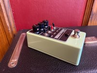
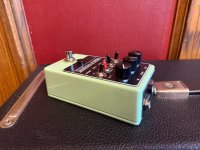
For this build I chose a beautiful powder coated light green Tayda enclosure. I tried different knobs but the black ones seemed to fit the build and I used black toggle covers for the on/off/ons and a red cover for the on/on voice switch. I used a 1kg footswitch and the Lumberg jacks. The LED is orange diffused. I used faceplates for the top jacks and pedal top. I hope PedalPCB has more faceplates made. I just love the professional look. I only do black graphics so having more plates would allow me to use dark enclosures. Because of the faceplate on this I could have used a dark enclosure. I think it is a very nice pedal and I dropped it off with some local players at Dave's Guitars in Milwaukee for testing!
I see one Derailer user made a Youtube video and compared this to a Dumble. It does have a good selection of sounds. Mine is clipping with Zenner 2.0s because I have not ordered the 1v8s. I have all diodes socketed for swapping. I think to get the best sound you will have to spend at least an hour. The high-cut center potentiometer is interesting. Turning left for highs and right to cut the highs. This thing can get very loud and very dirty. I always like an overdrive that allows me to get lows, and this pedal does that, On the vintage toggle the pedal behaves somewhat like fuzz at times, slightly flubby unless you engage a few switches. I can say I only played with it for about twenty minutes but I imagine if you have a sound that you are looking for you may be able to find it in this pedal.
For this build I chose a beautiful powder coated light green Tayda enclosure. I tried different knobs but the black ones seemed to fit the build and I used black toggle covers for the on/off/ons and a red cover for the on/on voice switch. I used a 1kg footswitch and the Lumberg jacks. The LED is orange diffused. I used faceplates for the top jacks and pedal top. I hope PedalPCB has more faceplates made. I just love the professional look. I only do black graphics so having more plates would allow me to use dark enclosures. Because of the faceplate on this I could have used a dark enclosure. I think it is a very nice pedal and I dropped it off with some local players at Dave's Guitars in Milwaukee for testing!
Attachments
Last edited:

 !!
!!
