
OD is Glorious
Well-known member
- Build Rating
- 3.00 star(s)
Edit: there may be an issue with R 37 and R 38. I was just reading this thread. Just recently I started following the board unless there was a note somewhere saying it was incorrect. Seems there’s a disconnect between the Pastel board and the build docs but no note on the build docs.
I pulled this one off of the scrap pile. I had it populated but I lifted the board in one spot and it needed attention so I set it aside. I remembered when I started that a member here told me to save my non-working boards because I would gain the skills to figure them out later. That was good advice and I have saved two different boards so far.
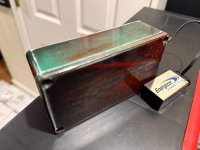
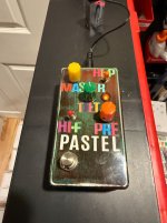
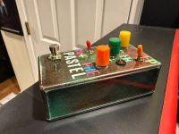
I had this enclosure completed last month and it was a labor of love that turned out sort of ok. For the enclosure I primed and then painted with about 5 different colors. I then sanded and exposed alternating layers, and added decals... then I cleared over everything and then buffed with compound. Looks a bit like a ransom note, but you can get the flavor of what I was trying to do. Colors...like crayon or pastel. Luckily I had most all of this work done weeks ago. For what this pedal does, there are just too many components and the build is too tight. I guess too tight for a guy with one fully functioning hand.
Too many resistors and 22u caps. The end result is meh. My least favorite circuit here is the Fudge Round Fuzz and I would add this one to my list of least favorite. It is flubby when you crank the preamp past 3:00. It gets hi/lo with switches and not too much else: either really screamy high, or incredibly low. It has some compressed distortion capability and some boost capability but other pedals do those things better.
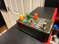
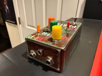
Beyond the paint, I added multi-colored buttons and colored switch caps. Inside the jacks are Lumberg and the LED is a 5mm Orange diffused. My deviation from build docs had to do with the hard-to-find 2N6429. I used MPSA18 in place of them and maybe that is the cause of the flub? I double checked all of my components. In any event it works and makes useable sounds.


I pulled this one off of the scrap pile. I had it populated but I lifted the board in one spot and it needed attention so I set it aside. I remembered when I started that a member here told me to save my non-working boards because I would gain the skills to figure them out later. That was good advice and I have saved two different boards so far.
I had this enclosure completed last month and it was a labor of love that turned out sort of ok. For the enclosure I primed and then painted with about 5 different colors. I then sanded and exposed alternating layers, and added decals... then I cleared over everything and then buffed with compound. Looks a bit like a ransom note, but you can get the flavor of what I was trying to do. Colors...like crayon or pastel. Luckily I had most all of this work done weeks ago. For what this pedal does, there are just too many components and the build is too tight. I guess too tight for a guy with one fully functioning hand.
Too many resistors and 22u caps. The end result is meh. My least favorite circuit here is the Fudge Round Fuzz and I would add this one to my list of least favorite. It is flubby when you crank the preamp past 3:00. It gets hi/lo with switches and not too much else: either really screamy high, or incredibly low. It has some compressed distortion capability and some boost capability but other pedals do those things better.
Beyond the paint, I added multi-colored buttons and colored switch caps. Inside the jacks are Lumberg and the LED is a 5mm Orange diffused. My deviation from build docs had to do with the hard-to-find 2N6429. I used MPSA18 in place of them and maybe that is the cause of the flub? I double checked all of my components. In any event it works and makes useable sounds.


Attachments
Last edited:


