
Rockman X100 Rev. 10 Schematic Release

Cybercow

Thanks for the quick reply back.

On your original X100 mode switch you showing bottom right corner how to hook up the Rockman original SW101 mode switching to your circuit, but I do not see how to connect your new one-of-four switching schematic.
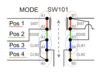
For the "One-of_Four" (radio button style) switching, the "A1 - A5" & "B1 - B5" values are what transpose over to the original SW101 diagram.
Do the two different one-of-four switching schematics do the same thing.
Yes, they are simply drawn out differently.
I do not have the CD4042 and it is not sold at Tayda, anyway to use CD4013
No. The CD4042 is critical for the "One-of_Four" (radio button style) switching. The CD4013 is a CMOS Dual D-Type Flip-Flop and the CD402 is a CMOS Quad Clocked D-Latch - they work entirely different from one another. Mouser, DigiKey and several safe eBay sellers have the CD4042.
 
Looking at the schematic then, would I still need the four diodes in the purple box and everything to the right? And the bottom schematic wiring would replace the wiring to the left of the four diodes in the purple box with no connection to Q1
 
Looking at the schematic then, would I still need the four diodes in the purple box and everything to the right? And the bottom schematic wiring would replace the wiring to the left of the four diodes in the purple box with no connection to Q1
Correct on both counts.
 
Last edited:
Cybercow

I just completed a vero board layout I created for your switching one of four logic switching circuit with the upper purple box with the four diodes and circuit to the right. It does switch between all four, but the clean sounds sound a not so clean.

Can you please let me know which circuit should each SW active (SW1 seems to be clean, SW2 seems to be edge, SW3 seems to be dist, and SW4 seems to be the other clean). Does this seem correct, and what clean is SW1 and SW4
 
Cybercow

I just completed a vero board layout I created for your switching one of four logic switching circuit with the upper purple box with the four diodes and circuit to the right. It does switch between all four, but the clean sounds sound a not so clean.

Can you please let me know which circuit should each SW active (SW1 seems to be clean, SW2 seems to be edge, SW3 seems to be dist, and SW4 seems to be the other clean). Does this seem correct, and what clean is SW1 and SW4
Here's a close up of a section of one of the diagrams from the first post in this thread. It's the X100 Mode switch mapping. It's what we used to build the pedals and it works. Of course you are free to wire it in any order you wish. Just keep the output pairs from the CD4052 chips (A1/B1, A2/B2, etc) together.

X100_Mode_Switch_Mapping_Diagram.png
 
Back
Top