Dream Fuzz (low output/ extreme bass)

evil.audio

New member
Hey everyone!

I’m working on a dream fuzz (ehx big muff op amp clone)

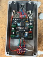
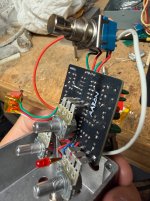
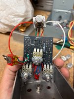
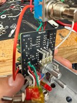
I’m pretty much out of ideas of what’s wrong with this thing. The LED turns on and It outputs sound however the signal is extremely low, very muffled, and very bass heavy. Nothing close to resembling a big muff! Bypass mode works fine.

So far I’ve tried:
  • Double checking every component value (hence the white paint pen everywhere)
  • Reflow soldering every component
  • Replacing the ICs
  • Replacing the 3PDT switch
  • Rewiring everything coming off the board
  • Measuring vcc pin on each IC which was about 8.6v-8.7v
  • Jamming cardboard and Kapton tape between the pots and the board to prevent shorts
Only hunches I have left:
  • voltage measured across the ground and SW solder pads on the bottom of the pcb was 7.5v which I thought was strange.
  • the tan resistors were from an old Amazon assortment kit I had laying around. Being carbon film maybe the tolerances are way off although I measured a few and they were very close to their listed values.
  • I might build an audio probe and trace the signal path?
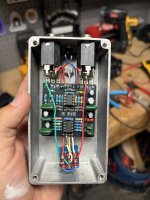
Wiring and soldering is a bit messy after ripping it out of its case so many times. I’ve successfully built a few pedal pcb projects but that being said I’m still pretty new to this and only have a multimeter for testing at the moment. Thank you to anyone who has any ideas! IMG_7289.jpeg IMG_7296.jpeg IMG_7298.jpeg IMG_7297.jpeg IMG_7299.jpeg
 
Is the lower pot insulated? If not, could be shorting some points
Edit. Missed that note. Though cardboard and kapton tape aren't exactly puncture proof.
 
Last edited:
Your best bet for that middle pot is a plastic dust cap. For now, pull it away from the board to eliminate the chance of the leads on the back of the board poking thru. All it takes is one tiny poke to cause issues like you're describing.

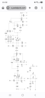
Definitely put together an audio probe. It's really easy. Follow along with the schematic and the traces you can see on the board.

7.5v at the gnd/sw is normal as that's the circuit for the LED and there is a 1.5v voltage drop when the LED is on.

Test your pots to make sure they are the correct value. Also test where the sweeper is at. Ie check for resistance from legs 1 to 2 and 2 to 3 and make sure it changes as you turn the pot shaft, and that the values add up to the total value of the pot.
 
Probe is the way to go. Kinda sounds like you have a wrong value cap that shifted a filter.
Probe pins 1 and 7 of IC1 and pin 6 of IC2.
Alight, I’ve put together a probe, I’ve only traced the audio path until pin 7 of IC1 which has no output. Pin 1 of IC1 does have a nice distorted output. I’m not sure what would cause the 2nd output of that opamp to fail but I’m going to replace the surrounding capacitors (c3,c4,c5) and see if anything changes!
 
Your best bet for that middle pot is a plastic dust cap. For now, pull it away from the board to eliminate the chance of the leads on the back of the board poking thru. All it takes is one tiny poke to cause issues like you're describing.

Definitely put together an audio probe. It's really easy. Follow along with the schematic and the traces you can see on the board.

7.5v at the gnd/sw is normal as that's the circuit for the LED and there is a 1.5v voltage drop when the LED is on.

Test your pots to make sure they are the correct value. Also test where the sweeper is at. Ie check for resistance from legs 1 to 2 and 2 to 3 and make sure it changes as you turn the pot shaft, and that the values add up to the total value of the pot.
Certainly, I don’t have dust covers but I’ve cut out some 1/16” plastic and I’ve taped it to the back of the middle pot just in case.

I’ve also tested all of the pots which add up to their respective values.

However it seems like the problem is originating before the signal reaches the pots anyway. The 2nd output of IC1 isn’t producing any sound (pin 7), however the 1st output is fine (pin 1). I don’t fully understand which caps/ resistors set the filter parameters on IC1 but I’m replacing c3,c4, and c5 to see if anything changes!
 
I'd do a couple things.
1)try another dual opamp
2)before insert the new opamp, check resistance between pin 7 and 8 to make sure there is not a bridge under the socket or elsewhere.
The first gain stage shouldn't be super distorted, unless your feed too hot of a signal in.
With no audio, what DC reading do you get between IC1 Pin 5 and ground?
 
Also, never take for granted that both half of an IC are used one after the other. A section could use the first half and the other half could be used at the end of the circuit.
 
what are you talking about?
There are 3 gain stages. A single and a dual opamp.
It's right there in the schem.
Holy crap ... I must have been still sleeping. I knew there was 3 gain stages but really thought there was two dual op with one that only one half was used ... and litterally thought I saw ic2 and ic2.2 !

Really sorry about the confusion.
 
I'd do a couple things.
1)try another dual opamp
2)before insert the new opamp, check resistance between pin 7 and 8 to make sure there is not a bridge under the socket or elsewhere.
The first gain stage shouldn't be super distorted, unless your feed too hot of a signal in.
With no audio, what DC reading do you get between IC1 Pin 5 and ground?
No bridging between pins 7 and 8. Between ic1 pin 5 and ground I’m getting 4.12v?
 
What does that audio probe look like?
Pin 1 of IC1 output shouldn't be very distorted, it's just a boost stage.
What are the voltages of all other IC pins?
Is the tone muffled regardless of the tone switch position?
 
Back
Top