zero's various pedal builds

PXL_20261025_060651872.jpg
PXL_20261025_060657414.jpg

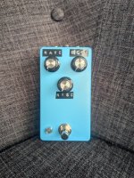
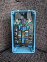
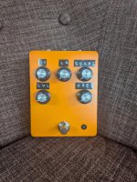
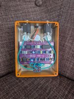
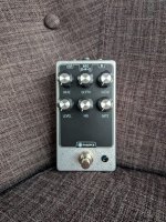
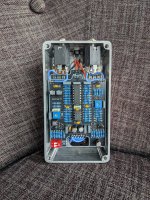
VIIB Vibrato - Love this one, sounds really cool.
Couple of annoying things while building - I had the wrong kind of LED, apparently a common anode type LED exists, and I had 10 of them. Luckily I had one single common cathode, so thats in there now.
bummer is that the red side is ridiculously bright, so I need to find the CLR. I dont really want to pull it all apart to do so though :(
I found a picture of someone else's build and set the trimmers to roughly where they were at so that I could start the bias, plugged it in and it immediately sounded pretty good so I guess I'll just leave them where they are.

All modulation should have intelligent relay.
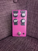
 
50851.jpg 50852.jpg

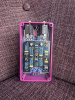
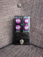
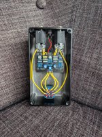
Pot and Kettle Pro
It was really nice that the first two j201s I dropped in this worked just fine, jfet pedals without trimmers make me nervous. Overall the pedal itself didn't really excite me though, I feel the Mach1 is now my pedestal pedal for low gain.
The knobs are a bit big and I had to use tweezers to apply the labels.
 
50859.jpg
50809.jpg

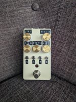
Mister Fuzz
Q1 random p416a at around 40hfe, 10ua leak
Q2 MP42b 85.9hfe 239ua
Q3 MP42b 92.1hfe 434ua

I tried to play satisfaction into it and I think it works. I changed volume to A500k as I think unity is below halfway, and C4 is 4.7nf for a little less harsh treble.
 

Attachments

  • 50860.jpg
    50860.jpg
    1,001.5 KB · Views: 3
Last edited:
51149.jpg
51150.jpg
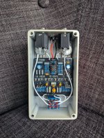
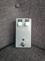
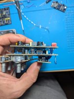
Lowtide Mini, with intelligent relay bypass

I put relay bypass in all my keeper pedals nowadays, I hate that click on a footswitch. So I desperately wanted to have it fit in the mini, and was never certain it was going to fit. Turns out it can, just needs to be under the pots.
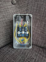
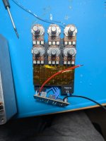
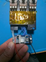
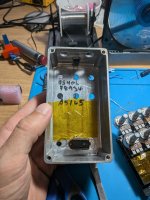
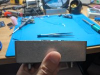
Some photos of construction, the tape is to stop shorts, I know this isn't the most certain of insulation but it's working for the moment.

51140.jpg
51142.jpg
Wiring was inverted so I had to twist all the wires over themselves

51143.jpg
Rough test fit. The tallest part was actually the 100uf cap, I think if you used a 5mm cap sideways that might have been slightly lower.

51144.jpg
Insulation in enclosure as well

51145.jpg
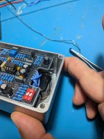
ICs are just over the level of the enclosure, but the lid has a little depth

51146.jpg

Probably the hardest part- getting the footswitch wires attached to the switch. Probably should have done that earlier, but I managed.

Biasing went fairly easily. 2.3v on that pin for BBD was spot on and gate as per this post.
 
Back
Top