A Blast from the Past - Custom Flanger

Chuck D. Bones

Circuit Wizard
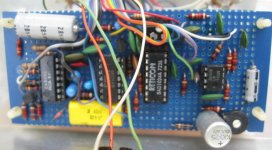
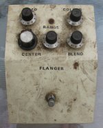
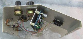
I built this in 1976 or 1977. It's basically an Electric Mistress with two more knobs. My brother found this in his garage. It's period-correct Electric Mistress right down to the Reticon SAD1024A BBD. Check the date code.

1976 Flanger (dirty) 02.jpg

1976 Flanger innards 02.jpg

1976 Flanger innards 04.jpg

Chips are (L-R):
RCA CA339 quad comparator
National Semi CD4013B
Reticon SAD1024A BBD
National Semi LM1458N dual opamp

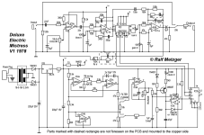
I'll post a schematic after I trace this one because the original hand-drawn schematic is long gone.

I have three other goodies that he gave back to me...
Roland AP-2 Phase II with an added DEPTH knob
Modd'ed Fender Blender
An original design two-knob opamp BMP using a rare (these days) Siliconix L144 triple micropower opamp.
 
Last edited:
I built this in 1976 or 1977. It's basically an Electric Mistress with two more knobs. My brother found this in his garage. It's period-correct Electric Mistress right down to the Reticon SAD1024A BBD. Check the date code.

View attachment 122506

View attachment 122507

View attachment 122508

Chips are (L-R):
RCA CA339 quad comparator
National Semi CD4013B
Reticon SAD1024A BBD
National Semi LM1458N dual opamp

I'll post a schematic after I trace this one because the original hand-drawn schematic is long gone.

I have three other goodies that he gave me back...
Roland AP-2 Phase II with an added DEPTH knob
Modd'ed Fender Blender
An original design two-knob opamp BMP using a rare (these days) Siliconix L144 triple micropower opamp.
The flanger looks much better than some professional builds I have seen from that period! Looks beautiful! Does it still work fine? Care to demo it? Cool stuff.
 
I built this in 1976 or 1977. It's basically an Electric Mistress with two more knobs. My brother found this in his garage. It's period-correct Electric Mistress right down to the Reticon SAD1024A BBD. Check the date code.

View attachment 122506

View attachment 122507

View attachment 122508

Chips are (L-R):
RCA CA339 quad comparator
National Semi CD4013B
Reticon SAD1024A BBD
National Semi LM1458N dual opamp

I'll post a schematic after I trace this one because the original hand-drawn schematic is long gone.

I have three other goodies that he gave me back...
Roland AP-2 Phase II with an added DEPTH knob
Modd'ed Fender Blender
An original design two-knob opamp BMP using a rare (these days) Siliconix L144 triple micropower opamp.
So rad!
 
Last night I checked out the wiring and power. I had made a 15VDC regulated power supply for it. Back in paleozoic, we ran everything on batteries. The 15V is then regulated down to 12V inside the unit, just like the EM. At some point, I'll probably replace the power jack with the standard 5.5mm negative center jack and run it on 18V. Today I plugged a guitar into it and it works! The taper is wrong on the SPEED pot and the CENTER pot has too much range. Easily fixed. Sounds just like an Electric Mistress.
 
Very cool. How come other Electric Mistress clones I see have way more ICs and parts? Are there more than one electric mistress circuits?
 
Knob functions:
SPEED is the LFO rate
COLOUR is the feedback or resonance control. At 10, there is enough feedback to sustain oscillations.
RANGE is the width of the sweep, similar to the EM's RANGE knob.
CENTER is the offset of the sweep. It has maximum effect when RANGE is turned down and no effect when RANGE is dimed.
BLEND is the wet/dry mix. 50/50 is around 8 on the BLEND knob.
 
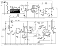
Here's a brief circuit description of how the Electric Mistress V2 (2nd schematic) works.
IC1A is the input buffer. IC1B is the pre-emphasis filter. Music has a much stronger signal at lower frequencies. The pre-emphasis filter increases the higher frequencies to even things out and maximize the BBD's dynamic range. There are a few Rs & Cs after the BBD that provide de-emphasis so that the overall freq response is flat and the noise is reduced. There is a few dB of gain variation from one BBD to the next. VR2 is a gain trim that allows us to set the overall gain to unity. The COLOR pot feeds back a portion of the BBD output back into the pre-emphasis filter. That's the entire audio path.
IC5 & the BC309 form a 12V regulator. These day's we'd use a 78L12. VR1 sets the DC bias on the opamps and BBD to maximize the BBD's headroom and minimize distortion.
IC4A is configured as an integrator and is part of the LFO. It generates a triangle waveform. IC4B's output flips positive when the triangle wave reaches the lower threshold. This puts flip-flop IC3A in the ON state, which causes the integrator to ramp the triangle wave in the positive direction. When the triangle wave reaches the upper threshold, it flips IC3A into the OFF state, causing the integrator to ramp in the negative direction and the cycle repeats. The RATE pot and the two caps in the integrator's feedback loops set the LFO freq.
The LFO's triangle wave is fed to the clock VCO (IC4C & IC4D) via the RANGE pot. This modulates the clock freq, which varies the BBD delay. Here's the clever part: we don't want the clock freq to ramp up and down linearly, we want the clock period (the duration of one clock cycle) to ramp linearly. The clock VCO does that by varying the threshold at which the clock cycle terminates and restarts. The BC177 transistor is configured as a current source. It charges the 470pF cap at a constant rate, producing a positive ramp at pin 6 of IC4C. That voltage is compared with the signal coming from pin 2 of the RANGE pot. When pin 6 is greater than pin 7, pin 1 switches to GND, which tells IC4D to also switch its output (pin 14) to GND. This rapidly discharges the 470pF cap, pin 1 goes high again and the cycle repeats. The VCO runs from about 20KHz up to around 250KHz. IC4C pin 1 connects to pin 12, the clock input of flip-flop IC3B. Every time that the clock input goes from low to high, the flip-flop's output flips to the opposite state. Pin 12 and pin 13 are compliments of each other. When one is high, the other is low. Whenever the clock input goes from low to high, they swap states. This creates the two phase clock that feeds the BBD.
 
Those schematics above are Electro Harmonix Designs. In 1976, I was an EE student at UCLA. I had a part-time job on campus building stuff for a PhD student. That gave me access to the engineering machine shop, which is where I drilled the chassis above and made the bracket that supports the board. There were plenty of electronics parts stores around then. One in particular, Formula International, imported parts from Taiwan. That year I shared an apartment with my best friend. We'd get high and keep the neighbors up playing guitar at all hours. He'd buy pedals and I'd talk him into letting me open them up and trace the circuits. There was a funk band living in the complex and I'd fix their gear in exchange for gear they didn't want anymore. I learned a lot studying other peoples' designs. Big Muff, Distortion+, EHX Black Finger, Roland Jet Phase, Foxx Fuzz Wah, MuTron III, Fender Blender... I'd read about BBDs. Commercial ones were just becoming available. When my roomie bought an Electric Mistress, I couldn't wait to trace it and see how it worked. It was a revelation. I mail ordered five SAD1024As. I think I paid about $10 each for them at the time. The flanger pictured above was the 2nd one I built. The first one I built, I stuck in a Foxx Fuzz Wah enclosure. It had better filtering than the EM. It worked great, but maybe too well. It didn't have that Electric Mistress razzzzzz tone. I took the BBD chip out and stuck it in the flanger you see above. I still have the Fuzz Wah flanger. It's missing a few parts besides the BBD, but could be resurrected.
 
Last edited:
They are not. The FB still has it's original knobs. One of the electronics stores I frequented, ITV, carried some surplus stuff in addition to new parts. Back around 1970, Fender made some prototype solid state amps. Those amps ended up at ITV, along with some spare parts. I bought a 60W amp along with a bunch of knobs and 1/4" jacks.
 
What a fantastic sorry! Thank you for sharing. That sounds like a really awesome environment, and you really made the most of it, tracing all three circuits and using that as a springboard to your own designs. Was there anytime around to collaborate with at the time or were you on your own?

(Separately, Fender solid state about prototype wow. How did that sound? Still have it?)
 
Back
Top