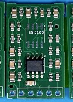
A new-production BBD, with added features!

I received a few of these from CabinTech this week. I decided to use this as my first excuse to also try adding JLPCB's PCBA service, so I put together a small (17x27mm) PCB with the circuit and components from the SSI 2100's typical application circuit. I set this up to connect out to a parent circuit through a pin header.

I don't pay more than the lowest shipping option, so I expect it will take a few weeks for these to show up.

SSI2100 App Circuit.png
 
Last edited:
I received a few of these from CabinTech this week. I decided to use this as my first excuse to also try adding JLPCB's PCBA service, so I put together a small (17x27mm) PCB with the circuit and components from the SSI 2100's typical application circuit. I set this up to connect out to a parent circuit through a pin header.

I don't pay more than the lowest shipping option, so I expect it will take a few weeks for these to show up.

View attachment 109421
Awesome. Looking forward to hearing your thoughts on the chip!
 
A set of these prototypes arrived yesterday while I was driving across the country. I think this is more of a "teaser" post. I am not going to have time to touch these for a while - the rest of life has decided to raise a crisis that takes priority...
 

Attachments

  • SSI2100.jpeg
    SSI2100.jpeg
    202.5 KB · Views: 26
A set of these prototypes arrived yesterday while I was driving across the country. I think this is more of a "teaser" post. I am not going to have time to touch these for a while - the rest of life has decided to raise a crisis that takes priority...
Well - quick assessment is the SMD board is not functional. Pfft. I have signal and clock going into the SSI2100, but am not seeing anything come out.

I have a couple of leads to check - one possibility is my clock is not suitable (SA555P setup for 86kHz and 48% duty cycle). I think this should be working but am going to try out a CD4047 as clock alternative.

Alternatively, and a bigger issue, is the VTbias capacitor SMD I used may not be suitable for the SSI2100. In this case, the board design is the problem and would need to be reworked. I would also probably add a location for a gain capacitor on the board when I revise.

If the alternative clock doesn't work, I will probably have to mount up an SSI2100 onto a carrier board and breadboard out the whole circuit...
Any update on this?
 
Any update on this?
No. I have been busy mostly with my professional work, and with things that are working a bit better. I did take a second look, and the second time I was measuring, I didn't see my input signal coming through to the output of the buffer OpAmp, but didn't have time to debug the new problem!

If you send me your address, I will drop one of these in the mail to you and you can have a look at it. I would welcome your thoughts or observations, since I would like to get the BBD working - I have a specific use case for a basic mono-to-stereo analog adapter to use delay to add space

My working theories are:

1. I didn't properly respect the data sheets recommendation on using an electrolyic for VTBias capacitor, and perhaps this needs to be taken off-board (for the current PCB with a proper electrolytic instead of the SMD capacitor I used here.
2. Using an SA555 as the timer is not adequate. I think these are better than a basic 555, but possibly the rise isn't fast enough or the signal isn't close enough to 50% duty, although I measured it quite close. I was going to stick a flip-flop in front of my timer to improve, whcih would only cut my timer down to around 43kHz, which is still wtihin reasonable performance for the BBD.

Gregory
For what it's worth, I saw someone on Modwiggler tried to play with this chip and found the chip wouldn't function with a less than optimal duty... which makes one sort of wonder why they didn't just put a flip-flop instead of an inverter inside the chip.

Also, don't know if it's of any use but have you looked at the vintage EHX Ambitron regarding mono-to-stereo?
 
Thanks for the tip, @Scruffie. Given that I already have my 555 clock setup on breadboard, I just have to read enough to run that through a 74HC74, which I also have. I am guessing from sketched circuit on ModWiggler, that the schmitt is dead simple (input, Qbar looped back, Q on to my BBD.

At some point, I can go back to my timing circuit and simplify it, too, removing the resistors I was using to try and force it to 50% duty cycle.
 
@Cybercow and others,
I made some progress today, but am stopping for the night before I am completely done with everything.
I put a 74HC74 into my clock signal pathway so that I could improve the clock to BBD. I started seeing output from the BBD that matched the input - but I don't have dual channel so I have no idea if it was truly delayed.

[long narrative version that mostly highlights my "knowledge"]
I cleaned up my timer and upped the frequency (i.e. got rid of the 27k/1k resistor pair I was using to get near 50% duty cycle) so that I had a 144kHz timer (10k/10k timer resistors) and a solid 72kHz clock to my BBD sub-board. But inconsistent output. Most notably, I was not seeing output from the op-amp going in to the timer. Now I happen to be powering this with a breadboard that has a 9V "starve"circuit that is feeding a 78L05 to regulate down to 5V to pass into the BBD board. And I messed with the power and I could see the OpAmp suddenly generate output as I dropped the power, and when I had output from opamp, I also have matching output from BBD. I switched my oscilloscope to DC mode, and re-read the BBD docs which show that the circuit wants a small signal (0.44Vpp max) vs the 1 and 2V signal I was testing with and it wants the OpAmp output biased to 3.2V, which I was most definitely NOT giving it.

My biased signal was only really showing output at 1.5ish V for the Vavg on the op amp output, although the Non-inv input pin (I think I have that correct) was otherwise biasing OK. So I pondered and realized that my little signal generator runs 0 to +V, not -V to +V, and I didn't put a coupling capacitor on this. Soo I begin to see where I am quite feeding the signal incorrectly, and I think this is why my op amp output looks clipped (duh), and when I move the voltage up I am just clipping (flatlining) the OpAmp output. I'm going to park for the night, though, but at least I know what to do next. Now I actually have no idea if my original timing circuit was a problem, but I am going to leave that alone, since the flip-flop divider definitely sharpens the clock shape and guarantees the right duty cycle.

TLDR
I was sending an overpowered signal that was DC biased into the op amp before the SSI2100, which was causing the OpAmp to clip instead of generating a suitable output. When I accidentally generated an output from the OpAmp that was "in-range", I could see a signal coming out of the BBD. Next step is putting a coupling capacitor on my test signal and seeing if I can get the OpAmp functioning as expected.
 
The LTC1799 clock chips arrived and so I fleshed out a full schematic to complete my breadboard testing of these new BBDs.

SSI2100_Development_Schematic_01.png
SSI2100_Dev_BB_03.jpg

I'll let you all know how things turn out after I get the breadboard completed with one of the freshly arrived clock chips added.
 
The LTC1799 clock chips arrived and so I fleshed out a full schematic to complete my breadboard testing of these new BBDs.

View attachment 114245
View attachment 114246

I'll let you all know how things turn out after I get the breadboard completed with one of the freshly arrived clock chips added.
I have looked at the LTC1799 as a simpler clock. Definitely interested to see how it works for you.
 
Oof. I have confirmed that I did, in fact, wire up the Op Amp inverting/non-inverting inputs backwards on my mini-board. So much for QC check before sending of to JLCPCB 😜. Walking this backwards, it looks like the SSI2100 data sheet shows the + an - in the opposite arrangement from KiCad's default behavior.

I just did a quick SPICE simulation, and yeah, reversing the inputs basically sends the op amp output to 5V.

I know it's not to be trusted without verification, but ChatGPT tells me:
signal feedback to inverting input = stable, linear amplifier,
signal feedback to non-inverting input = comparator/latch.

Yep. I built an unstable op-amp latch...

I am going to attempt microsurgery to revers the leads.

Sim.jpg
 
It lives!

I was able to clip and jumper the input side of the OpAmp on my little board and the SSI seems to be working! Cool. When I went to jumper the output side, though, I have bunged the chip too much. I think I am going to just desolder and remove it and start with a fresh TL072 with jumpers on the 4 flipped pins. Connecting them to other SMD's was easy enough, since the resistors and capacitors have solid ends.

I revisited my PCB layout and am thinking about what other changes I want to make, but I feel like it's ready for a revision. Currently I am thinking of:
1. fixing the routing to Op Amp
2. adding either on-board pads for an electrolytic for C7, the bias capacitor or maybe just leaving this in place but adding pads so I could lay an axial capacitor over top of the board if I want it
3. putting some labels on the connections!

I also have picked up some SMD SA571 Companders and I am thinking that maybe I should work up a design to replace the Op Amp with the compander.

-G
Hooray! What are the noise levels and headroom like? Are they as poor as the datasheet indicated or was it being conservative?
 
Back
Top