Adding a blend to a Promethium (HM-2)

@benny_profane
Promethium is wired directly to DC jack and so is the blend board.

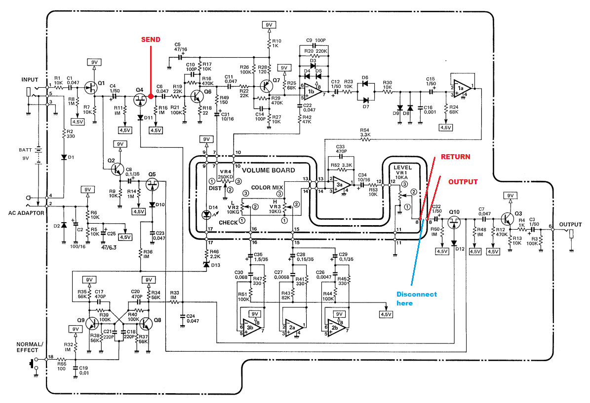
Did some more experimenting today and I isolated the clean signal from the blend and sent it directly to the tip of a separate output which was grounded to the pedal jacks, and there was no distortion bleed over so that's good. When I hooked the clean signal back up to lug 1 of a potentiometer with the distortion on lug 3 and output of 3PDT on 2, the bleed was back.
Even when I disconnected the promethium from lug three there was still some bleed which was boggling my mind. However, if I shunted the return from promethium to ground, no more bleed.

I realized that the way I was testing this might have been conflating some of these issues because I was using a breadboard to make some of these connections and I also left some wires hang. I accidentally stumbled upon something cool when I was moving the output tip connection around on my breadboard... It was picking up the signal from the disconnected distortion return when I moved the end of the jumper close to the hanging promethium return wires. I guess I made myself an antenna. I'm thinking something like this must have been going on yesterday when I disconnected the send and return from the promethium and was still picking up some signal.

Gonna probably try the JMK panner or paralyzer soon since shunting the other signal to ground seemed to make this problem disappear in my testing. Honestly, at this point it is really the perfectionist in me because the amount of bleed when the pot is on fully clean isn't horrible and I don't see why I would want to run it fully clean anyway, but that is beside the point.
 
Last edited:
Update:

Built the JMK Paralyzer on stripboard.

I hardwired send tip 1 to promethium IN and return tip 1 to promethium out. I connected send tip 2 to the tip of a mono switch jack, send jack's switch to return jack's switch, and the return jack's tip to return tip 2 on Paralyzer. (also connected the two jack's grounds together then to the regular output jack ground)

When nothing is plugged into the send and return jacks I added, it just blends a clean signal. When something is plugged into to loop, you can blend a separate distortion pedal or effect parallel to the promethium. No bleed. It works!!!

The only problem is the promethium signal tends to overpower the parallel clean/fx loop until the pot is turned almost all the way to the blend side. I'm sure it could be remedied by adding a boost for the loop somewhere. It could probably also benifit from a phase switch since some pedals are going to invert.

Regardless, it works!!!

I used this stripboard layout of the Paralyzer:
 
I modded my real HM-2. The schematic at the Peperspedals link shows it wired right in between the flip flop switching (Q4 & Q10). The Promethium also has the in and out buffers, so it should work the same.
HM-2%2BBlend%2Bmod%2BSchematic.png


You can see where "send", "return" and "output" are wired, when using the Tagboard layout he recommends.
http://tagboardeffects.blogspot.com/2012/01/mini-blend-jfet.html
Attached is a schematic of the blending circuit, though Peppers used different values.


On the Promethium:
"send" between Q1 and C2 to the blend board, which then goes to blend pot #1
"return" from volume #2 to blend pot #3 (notice " disconnect here")
"output" from blend pot #2. I'm not sure if YOU need that 1uf (C32 on the Boss schem) as you're using true bypass.
 

Attachments

  • image.jpg
    image.jpg
    1.2 MB · Views: 10
  • image.jpg
    image.jpg
    1.3 MB · Views: 8
  • image.jpg
    image.jpg
    1.6 MB · Views: 6
  • image.jpg
    image.jpg
    1.6 MB · Views: 8
I modded my real HM-2. The schematic at the Peperspedals link shows it wired right in between the flip flop switching (Q4 & Q10). The Promethium also has the in and out buffers, so it should work the same.
HM-2%2BBlend%2Bmod%2BSchematic.png


You can see where "send", "return" and "output" are wired, when using the Tagboard layout he recommends.
http://tagboardeffects.blogspot.com/2012/01/mini-blend-jfet.html
Attached is a schematic of the blending circuit, though Peppers used different values.


On the Promethium:
"send" between Q1 and C2 to the blend board, which then goes to blend pot #1
"return" from volume #2 to blend pot #3 (notice " disconnect here")
"output" from blend pot #2. I'm not sure if YOU need that 1uf (C32 on the Boss schem) as you're using true bypass.
I ended up making a Simple FET Blend on a trial and error run but I’m still VERY CONFUSED as to how to wire this thing lol.
Anyone have some pointers?
 
I ended up making a Simple FET Blend on a trial and error run but I’m still VERY CONFUSED as to how to wire this thing lol.
Anyone have some pointers?
What layout did you use for the blend? Maybe this will help you. I know you don't have the breakout board for your 3PDT which adds to the confusion.
I wired the Split 'n Blend to the Promethium and 3PDT as follows:
  • SNB IN to 3PDT board IN
  • SNB Send to promethium PCB IN
  • Promethium PCB OUT(return) to Blend lug 3
  • SNB blend 1(or OUT on mask audio's blend) to Blend lug 1
  • 3PDT board OUT to Blend lug 2
 
@delackattack

If it is this one then:

Connect 9v and ground from SB(simple blend) to appropriate DC jack lugs.
Desolder the wires from Prom(ethium) IN and Prom OUT, but keep them attached to the 3PDT
Connect the wire from 3PDT that you desoldered from Prom IN and connect to SB IN
Connect the wire from 3PDT that you desoldered from Prom OUT and connect to SB OUT
Connect Prom IN to SB SEND
Connect Prom OUT to SB RETURN

Pretty sure that is right. It's confusing.
This is the exact one! Im gonna wire it up after work
 
@delackattack

If it is this one then:

Connect 9v and ground from SB(simple blend) to appropriate DC jack lugs.
Desolder the wires from Prom(ethium) IN and Prom OUT, but keep them attached to the 3PDT
Connect the wire from 3PDT that you desoldered from Prom IN and connect to SB IN
Connect the wire from 3PDT that you desoldered from Prom OUT and connect to SB OUT
Connect Prom IN to SB SEND
Connect Prom OUT to SB RETURN

Pretty sure that is right. It's confusing.
I'm totally out of my depth here, but wouldn't you want to get your 9v for the buffer from the power filter section of the circuit rather than direct from the DC jack?
 
@delackattack

If it is this one then:

Connect 9v and ground from SB(simple blend) to appropriate DC jack lugs.
Desolder the wires from Prom(ethium) IN and Prom OUT, but keep them attached to the 3PDT
Connect the wire from 3PDT that you desoldered from Prom IN and connect to SB IN
Connect the wire from 3PDT that you desoldered from Prom OUT and connect to SB OUT
Connect Prom IN to SB SEND
Connect Prom OUT to SB RETURN

Pretty sure that is right. It's confusing.
I just got done wiring this up like such and it works like a charm.
 
I'm totally out of my depth here, but wouldn't you want to get your 9v for the buffer from the power filter section of the circuit rather than direct from the DC jack?
Good catch, I just assumed the blend did because most of the layouts on that website include power protection.
 
I just got done wiring this up like such and it works like a charm.
Mike is right. You should probably get 9v from the promethium board instead because there is no power protection or filtering on that board.

I can try to walk you through this, but this might be a good learning experience for you if you don't know how to read a schematic yet. Where to tap the +9V from might depend on the location of this board in your enclosure. Any connection on the promethium schematic that says VCC (in this case, this doesn't apply to every schematic) is diode protected and filtered +9V power. Directly off the pad of where the cathode(stripe) of D8 is connected might be the closest place if you already have a wire going to the DC jack positive. There are a few ways you can do this, but a quick and dirty way would just be to solder a wire to this pad under the board but be careful not to have any exposed wire that could short out something under there. You could actually solder it to the top of the board if you wanted but it is ugly and you might scorch some components in the process.
 
Last edited:
So where would the power filter be on the Promethium?
It's this guy right here. You can see the 9v (VCC) supply rail and the 4.5v. (VREF). This is a circuit block that is common, for the most part, to lots of these pedals. It's just the power plant for effects supplying whatever a particular circuit block or element needs, (9v+, 18v+, 9v-, 4.5v+ or -, etc). You can figure out what kind of power supply is being fed into a circuit block by paying attention to those little flags (VCC, VREF, etc).

I suspect you want to tap the 9v rail, but again, out of my depth.
promethium.png

@fractal33, his offboard buffer will probably have a 9v+ and a ground coming off of it. Wouldn't he want to take power off the 9+ rail and elevate the ground by attaching it to the negative rail? Have I got that right?

The buffer he's describing probably works a lot like PedalPCB's simple JFET buffer:
simple jfet.png
 
Last edited:
So I’m coming way late to the party, but I’ve built a couple standalone clean blend pedals as well as added one to an OCD build and by far, the best one that I have used was one called the “Schooner” designed by a familiar face in these parts @jubal81. The other one that I have used was from nucleonfx based on the schooner, but it oscillated terribly unless both pedals were powered on isolated sources. I think the difference was that jubal81s design used a rail splitter, I believe for a virtual ground. I have the schematic if he is ok with me posting it? @jubal81 is that ok?
 
So I’m coming way late to the party, but I’ve built a couple standalone clean blend pedals as well as added one to an OCD build and by far, the best one that I have used was one called the “Schooner” designed by a familiar face in these parts @jubal81. The other one that I have used was from nucleonfx based on the schooner, but it oscillated terribly unless both pedals were powered on isolated sources. I think the difference was that jubal81s design used a rail splitter, I believe for a virtual ground. I have the schematic if he is ok with me posting it? @jubal81 is that ok?
That's fine. If I were to do it over again, I would use a very different circuit, though.
Adding a clean blend needs to be considered on a pedal-by-pedal basis because a lot of circuits flip the phase.
 
I think the analogman site may have a listing of pedals and circuit topology that are known phase flippers.
 

Attachments

  • Schooner-Doc.pdf
    232.6 KB · Views: 8
Have to admit, I gave in and got a HM Demon. Gnarly version of an HM-2. Complete with a Clean/Blend knob. :D

 
It's this guy right here. You can see the 9v (VCC) supply rail and the 4.5v. (VREF). This is a circuit block that is common, for the most part, to lots of these pedals. It's just the power plant for effects supplying whatever a particular circuit block or element needs, (9v+, 18v+, 9v-, 4.5v+ or -, etc). You can figure out what kind of power supply is being fed into a circuit block by paying attention to those little flags (VCC, VREF, etc).

I suspect you want to tap the 9v rail, but again, out of my depth.
View attachment 19986

@fractal33, his offboard buffer will probably have a 9v+ and a ground coming off of it. Wouldn't he want to take power off the 9+ rail and elevate the ground by attaching it to the negative rail? Have I got that right?

The buffer he's describing probably works a lot like PedalPCB's simple JFET buffer:
View attachment 19988
Man my head has been all over the place but I'm pretty sure It doesn't matter where the ground is connected in terms of jack vs promethium as long as he is tapping the +9 after the protection diode on the promethium.
 
Back
Top