The point of breadboarding is to see if your blender still works as it should. Does it have 9v where it's supposed to, does it have half voltage where its supposed to, is the electrolytic still functioning. That is a separate issue from how to fly this circuit into the host pedal. And I think how you could most effectively wire it is covered in this thread by someone else who is using the exact same blender circuit that you are using (Post #21 and on).
You could actually use the breadboard to test this as well. Just clip in wires to the suggested locations in the host pedal and see what happens. You can fly +9 volts and ground from the host pedal to the breadboard power rail. And then start the experiment.
Your 3pdt is just a switch that drops the blender circuit in and out of the host pedal on command, right? The 3pdt had to be connected to the host circuit somehow. But it sounds like what you are trying to do is make the blender circuit always on while the pedal is on, so adding an additional 3pdt may not be the right solution for you.
But now that I think about it, it seems like you could get filtered 9v and ground from a 3pdt PCB pad if you are using them, since they are getting their 9v from the circuit's power rail. This guy, as just one handy example, has additional grounding points and 9v power takeoff. (I'd be curious as to whether you could grab 9v from the LED circuit somehow so that when the host pedal is turned off, the blender circuit is also turned off. That circuit takes a signal from the "LED_BLK across a dropping resistor to the anode and cathode pads. Wouldn't that mean that there's 9 volts on the LED_BLK solder pad when the pedal is on? Hmm.)
View attachment 20185
Anyone else want to weigh in here?
I know we are late in the game here, but this also might be a good project to take the the Troubleshooting forum. Might get more experienced eyes on the problem.
(also, the thing that's been nagging at me is your wires. You have too many of them. That's why it looked so odd.
View attachment 20187
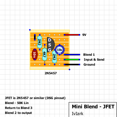
Your input and send are the same thing. You are scavenging a guitar signal from the host pedal so that the blender can process it. Only one wire comes into the circuit, not two. Then when you've got the signal and the circuit has done its magic, you send it back. Wiring pots always confuses me, but this thread will explain all that.)

tagboardeffects.blogspot.com


