
Aion Fx Theseus issues - King of tone

eurobailey

Active member
I built the aion fx KOT about 4 years ago and its been the bane of my pedal building journey!!!

The first time my issue was a solder bridge on the switch. Once fixed, the pedal worked however on side B i get the boost and drive settings but not the distortion setting. On Side A i get all three settings working as they should.

My tests so far have been checking FV of the diodes in circuit (no power) to ground and they seem ok. The hard clipping diodes are 1n914 in my build.

I have also checked continuity between the diodes and the switch. So i get continuity with the switch UP or DOWN with the respective diodes.. which seems incorrect however i get this on Side A and B and have no issues with Side A?

i am assuming i have a faulty switch or a solder bridge somewhere but i am a bit stumped as what my next move should be? Would love any suggetions.

Today I unsuccessfully tried to remove the dip switch… I will try again tomorrow but also wondering what else I can try to get this to work ? Someone suggested running a wire on both sides of the “hard clipping “ switch to permanently have the diodes in the circuit but this didn’t seem to have any impact.

I am using Revision A from aion FX. This is the schematic.
 
I've had two Aion PCBs with defective solder traces, on their MT10 clones.

I suggest you use a DMM set on resistance and beep and check for continuity between the DIP switch points (testing the switch itself) and then point to point through the path of the diodes. Replace the switch if you find it does not work, and jumper any 'open' circuit traces.
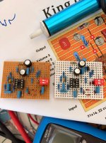
I felt like I did this and didn’t really get any conclusive evidence ! I seemed to get continuity where i should but the issue was still present. As a result, I cut my losses… I salvaged what I could from the build and I’ve started repopulating on stripboard ! About 75% of the way there!

I’ve decided to socket the second channel hard clipping section and try some bat 41 ones in there for a bit more grunt on the distortion . I was thinking maybe asymmetrical clipping as well. Any thoughts here anyone?
 

Attachments

  • IMG_2624.jpeg
    IMG_2624.jpeg
    688.7 KB · Views: 1
I felt like I did this and didn’t really get any conclusive evidence ! I seemed to get continuity where i should but the issue was still present. As a result, I cut my losses… I salvaged what I could from the build and I’ve started repopulating on stripboard ! About 75% of the way there!

I’ve decided to socket the second channel hard clipping section and try some bat 41 ones in there for a bit more grunt on the distortion . I was thinking maybe asymmetrical clipping as well. Any thoughts here anyone?
I've experimented a lot with clipping diodes and my ears like subtitle asymmetrical clipping, which is more 'amp like'. Drastic asymmetry (say a 1N4148 paired with a BAT41) has a broken sound that interferes with sustain (a unique and usable sound to some players). I also prefer symmetry with soft clipping and asymmetry with hard clipping.
Here are some combinations that I like:
- Soft Clipping: BS170 (MOSFET transistor around 0.6vf) paired with a 1N4148 (about 0.7vf), combined having 0.1vf difference in symmetry.
- Soft Clipping: BAT41 + 1N34A (around 0.6vf) paired with a 1N4148 (about 0.7vf), combined having 0.1vf difference in symmetry.
- Hard Clipping: a Red LED paired with a Yellow LED having about 0.4vf difference in symmetry.
- Hard Clipping: 1N34A + 1N5817 (0.55vf) paired with BS170 (0.6vf), with 0.15vf difference in symmetry.
- Hard Clipping: 1N4148 (0.7vf) paired with a BS170 (0.6vf), for a 0.1vf difference in symmetry.

Be aware when designing, that asymmetry is accomplished through components in three major ways:
- The difference in vf (the amount of voltage required to begin clipping) for 'clippers'.
- Speed at which a component reacts. An example for clippers, is Schottky diodes are very fast and MOSFETS are slow. For an Dual Op Amp
IC example, a MC1458P has a very slow slew rate of 0.5V/uS compared to a fast and quiet OPA134, that has a slew rate of 20.0V/us. Transistors
are too many to mention, but my guidance rule is silicon and germanium are fast and FETs and MOSFETs are slower.

For reference: https://www.guitarpedalx.com/news/gpx-blog/a-brief-hobbyist-primer-on-clipping-diodes
 
I've experimented a lot with clipping diodes and my ears like subtitle asymmetrical clipping, which is more 'amp like'. Drastic asymmetry (say a 1N4148 paired with a BAT41) has a broken sound that interferes with sustain (a unique and usable sound to some players). I also prefer symmetry with soft clipping and asymmetry with hard clipping.
Here are some combinations that I like:
- Soft Clipping: BS170 (MOSFET transistor around 0.6vf) paired with a 1N4148 (about 0.7vf), combined having 0.1vf difference in symmetry.
- Soft Clipping: BAT41 + 1N34A (around 0.6vf) paired with a 1N4148 (about 0.7vf), combined having 0.1vf difference in symmetry.
- Hard Clipping: a Red LED paired with a Yellow LED having about 0.4vf difference in symmetry.
- Hard Clipping: 1N34A + 1N5817 (0.55vf) paired with BS170 (0.6vf), with 0.15vf difference in symmetry.
- Hard Clipping: 1N4148 (0.7vf) paired with a BS170 (0.6vf), for a 0.1vf difference in symmetry.

Be aware when designing, that asymmetry is accomplished through components in three major ways:
- The difference in vf (the amount of voltage required to begin clipping) for 'clippers'.
- Speed at which a component reacts. An example for clippers, is Schottky diodes are very fast and MOSFETS are slow. For an Dual Op Amp
IC example, a MC1458P has a very slow slew rate of 0.5V/uS compared to a fast and quiet OPA134, that has a slew rate of 20.0V/us. Transistors
are too many to mention, but my guidance rule is silicon and germanium are fast and FETs and MOSFETs are slower.

For reference: https://www.guitarpedalx.com/news/gpx-blog/a-brief-hobbyist-primer-on-clipping-diodes
Thanks Man this is great . I am also wary of not going down a crazy rabbit hole (which i am known to do!!). I want to have more distortion than the stock circuit but doesnt have to be crazy amounts. My rationale for the Bat 41's originally is that they will compress harder than the 1n4148 but if i have 3 in an assymetrical config i will get a little bit more volume (for the loss of some compression as well).

In regards to your comments around mixing different diodes together with different FV, don't i already get this when i use an assymetrical configuration? e.g one side clips at .4v (normal bat 41) and the other side with 2 bat 41 in series clips at .8v? I know the bat 41 have a slightly softer knee than some silicone diodes which can make them a tad less harsh as well?
 
Back
Top