Aionfx Obelisk/The Brown Sound

Audandash

Well-known member
Build Rating
5.00 star(s)
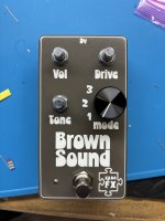
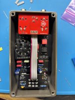
Well this is probably the last of my summer projects. It’s the Aionfx Obelisk. Its an overdrive based on the “brown sound” of the 60’s and 70’s. Also know as and overdrive, lol. Originally a Lovetone pedal which generally is all I need to want to build it. I had no expectations going in and was impressed with the results. I like the rotary dial to get some different tonal options. Seems like you can dial in some pretty mellow OD sounds as well and get pretty damn dirty. I have a feeling it will stay on my board for a few weeks anyway. OD’s to me are generally a flavor of the week deal. This is not a nasty flavor. Worth a build. I am out of 15mm knobs so I had to go with the black marker to get by :) IMG_5167.jpeg IMG_5169.jpeg
 
Yes I have been watching out for the PPCB flush mount version to get back in stock. It has been a while…
 
Your friendly proprietor has something like this available: https://www.pedalpcb.com/product/pcb429/

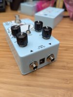
It takes the tayda panel mount 1/4 audio jacks and this DC jack. With a drill pattern like this from tayda, the results look quite nice!
View attachment 100266

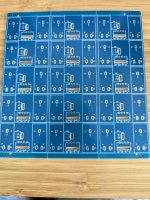
Yes he does and I’m not trying to short Robert. These are just a pin friendly layout specifically for the aionfx boards instead of ppcb boards. I make my own boards as well for ppcb projects with a pinout for them but haven’t shared it for that very reason. I certainly don’t want to offend.
 
Last edited:
For those who want to know the color is glimmer brown sugar. It was my first time trying it. It's a pretty solid effort. The picture doesn't really do it justice.
 
Looks really clean! Is there any chance of making the I/O board work with just round holes? Maybe washers inside for the 1/4” jacks?
 
Looks really clean! Is there any chance of making the I/O board work with just round holes? Maybe washers inside for the 1/4” jacks?
I am sure you could make it work but it would be a pain to wire up the power. You would end up with long power leads or just hope you never have to take it out, lol. The main appeal to this method, for me anyway, is to get that nice flush square power jack look. It adds a professional looking touch. It also makes it where if you have to troubleshoot you can drop the whole circuit out, jacks and all without having to desolder anything.
 
Looks really clean! Is there any chance of making the I/O board work with just round holes? Maybe washers inside for the 1/4” jacks?
I did build some IO boards like that that can use only round holes (so you can do it at home with a drill (press)). Instead of the jack for the power, it has a spot for a 2-pin JST connector, then you can solder the JST header to one of these types of DC jacks. This way you can at least theoretically remove the IO board without desoldering by disconnecting the power header. I really hate soldering wires to lugs though, so I've mostly just switched to the fancy rectangle tayda drills unless I'm in a rush with prototyping.

PXL_20250801_185811450.jpg
 
I did build some IO boards like that that can use only round holes (so you can do it at home with a drill (press)). Instead of the jack for the power, it has a spot for a 2-pin JST connector, then you can solder the JST header to one of these types of DC jacks. This way you can at least theoretically remove the IO board without desoldering by disconnecting the power header. I really hate soldering wires to lugs though, so I've mostly just switched to the fancy rectangle tayda drills unless I'm in a rush with prototyping.

View attachment 100316
That's an interesting idea! I've been toying with the idea of an I/O board that would mount vertically (90° to the effect PCB) so that I could use open frame Nuetrik jacks and a DC jack with external nut. I haven't bothered to develop the custom footprints required, though.
 
Back
Top