

Aleph Null
Well-known member
This design started out as an experiment with reverse biased transistors. For some reason, reversing a PNP transistor in a negative-ground circuit made it feel like the transistor was right side up again. Alcubierre makes sparkly overdrive, broken speaker, angry bumblebee, distortion, and gated fuzz sounds.

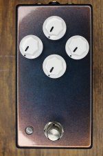
The enclosure is Alexandrite from Stomp Box Parts. It’s hard to capture. Sometimes it’s brown, sometimes purple or blue. The warped knob layout felt right for a warped circuit.
It’s a pretty simple design. The PCB offers lots of room to realize the negative space.
If you find this schematic hard to read, I’d recommend holding it upside down and looking at it in a mirror. I stuck to a 2N3906 transistor for Q1 because I was already using them other places in the circuit. Q1 is a basic boost, essentially an LPB-1. Gain is an adjustable emitter bypass capacitor. The bias network is dialed in to get the most headroom out of the 2N3906. The transistor doesn’t know that it’s not getting -9V on the emitter. It just knows that it’s seeing the right voltage potential between the collector and the emitter.
Q2 and Q3 are actually reversed biased. They have a modest amount of gain this way (maybe 4X). Most importantly, the harmonic content of the clipping is different than anything I’ve heard before. With Warp all the way down, the transistors are biased very close to the middle of the supply voltage. As Warp is turned up, the bias shifts down. This reduces headroom and makes the clipping progressively more asymmetric. Above noon, Q2 and Q3 are so miss-biased that they shut off and start to act more like diodes, creating a gating effect. The reverse bias stages are followed by a simple Tone control. The range is modest, just enough to tame the highs without drastically altering the sound.
I love that everything about it is bass ackwards: it uses PNP transistors, but is daisy chain safe; instead of slamming the signal into the power rails, it slams the power rails into the signal; you can run it at 18V, but there’s less headroom. I was surprised at how versatile this circuit ended up being, especially for something that looks like it could have been a fuzz design from the 60’s.
Here’s a demo:
As always, I have extra PCBs. If you're interested, just DM me!

The enclosure is Alexandrite from Stomp Box Parts. It’s hard to capture. Sometimes it’s brown, sometimes purple or blue. The warped knob layout felt right for a warped circuit.

It’s a pretty simple design. The PCB offers lots of room to realize the negative space.

If you find this schematic hard to read, I’d recommend holding it upside down and looking at it in a mirror.
I stuck to a 2N3906 transistor for Q1 because I was already using them other places in the circuit. Q1 is a basic boost, essentially an LPB-1. Gain is an adjustable emitter bypass capacitor. The bias network is dialed in to get the most headroom out of the 2N3906. The transistor doesn’t know that it’s not getting -9V on the emitter. It just knows that it’s seeing the right voltage potential between the collector and the emitter.Q2 and Q3 are actually reversed biased. They have a modest amount of gain this way (maybe 4X). Most importantly, the harmonic content of the clipping is different than anything I’ve heard before. With Warp all the way down, the transistors are biased very close to the middle of the supply voltage. As Warp is turned up, the bias shifts down. This reduces headroom and makes the clipping progressively more asymmetric. Above noon, Q2 and Q3 are so miss-biased that they shut off and start to act more like diodes, creating a gating effect. The reverse bias stages are followed by a simple Tone control. The range is modest, just enough to tame the highs without drastically altering the sound.
I love that everything about it is bass ackwards: it uses PNP transistors, but is daisy chain safe; instead of slamming the signal into the power rails, it slams the power rails into the signal; you can run it at 18V, but there’s less headroom. I was surprised at how versatile this circuit ended up being, especially for something that looks like it could have been a fuzz design from the 60’s.
Here’s a demo:
As always, I have extra PCBs. If you're interested, just DM me!
Attachments
Last edited:

