Paul.Ruby
Well-known member
Since some interest was shown in PCBs with only the drive channel, I've made a project at PCBWay... These are stand-alone, so include everything needed to make a drive-only pedal.
The PCB project is shared on PCBWay here:
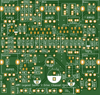
There are links to interactive BOMs on that page as well as schematics for each version I've drawn up. Since it's generic, it can be used for any of the AMT Legend Series II drive channels. But, I've only drawn up the C2, E2, K2, M2, O2, P2 and R2.
The PCB project is shared on PCBWay here:
AMT Legend Series II Drive Channel ONLY - Share Project - PCBWay
This PCB can implement any of the AMT Legend Series II drive channels. Does not include the clean channel or cab sim. This will fit easily in a 125B case.I also have a PCB that includes the clean chan...
www.pcbway.com
There are links to interactive BOMs on that page as well as schematics for each version I've drawn up. Since it's generic, it can be used for any of the AMT Legend Series II drive channels. But, I've only drawn up the C2, E2, K2, M2, O2, P2 and R2.
") I also recall seeing some russian website with the theory behind this design, but can't for the life of me find the link again.
I also recall seeing some russian website with the theory behind this design, but can't for the life of me find the link again.

