Paradox916
Well-known member
I definitely dig your concept.My pedal is taking shape.
Based on a PedalPCB Angry Andy (with somewhat random and unorthodox modifications to components as befits the context)
View attachment 43735
I definitely dig your concept.My pedal is taking shape.
Based on a PedalPCB Angry Andy (with somewhat random and unorthodox modifications to components as befits the context)
View attachment 43735

 .
.


 .
.


Thats fantastic! But it’s still MarchMy contribution for Autism Awareness month: Autistic Andy.
Well, this was ambitious...
I really grasped the theme and there are a lot of spectrum related metaphors going on here. My oldest son is a high functioning autistic now but was very much a handful growing up. More scary stories and sleepless nights than I can even remember. Looking back at my life and even just assessing my current self in the light of what I have learned it is abundantly clear to me that I and my father are both on the spectrum as well.
Not disabled, but certainly OTHER-abled. I like how Edward Hallowell speaks of ADHD as more "Attention Surplus Disorder" rather than "Attention Deficit Disorder."
Ausie's have their guts on the outside, have little concern for conventions, and are hyper focused on the things that interest them, but also readily jump from one rabbit hole to the next. And the way they look at the world is often completely obtuse and foreign to others.
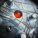
So what I settled on for this build was a drive pedal with switchable clipping, but with the diodes on the outside... I got these crazy-vintage germanium diodes from Nathan at Sushi Box FX and knew I had to do something special with them. I spent at least an hour twisting them to fit the design. The circuit is a PedalPCB Angry Andy but i bucked the spec sheet and used a 5532 for the IC, and orange LEDs for the other clipping diode set.
When the LEDs are the active diodes, they flash and flicker which is pretty sensational looking IMHO. The germaniums are suspended on solid 26 gauge wire, threaded through heat shrink all held in place by hot glue. The diodes are then remote wired to the PCB pads with an octopus of jumpers.
I used my "standard" orange marble lighting with vellum diffused backlight. I accidentally drilled the marble hole off center but I actually reallly like where it landed. The LED pads are at the complete opposite end of the board so I same up with a very unconventional (even for me) wire run and suspension tree.
I really like sticking foot switches in the corner of the pedal so I had no problem doing this to give more space to get groovy with the diodes, plus, it gave me a great excuse to do some equally crazy racetrack wiring of the 3PDT.
The design and labels were caustic soda etched for a record long 50 minutes for super-deep etch. And of course I got creative with the knob labels.
PCB assembly took about 20 minutes, but there are about 8-9 hours in total effort in the pedal
I hope you all like it. I think it is super cool. Definitely represents the height of my pedal craft.
AND.... It worked the first time I plugged it in... <boom>
View attachment 43771
View attachment 43775. View attachment 43776
View attachment 43779
View attachment 43772
View attachment 43773. View attachment 43774
View attachment 43778
View attachment 43780
 . No worries… the diodes are crazy! Very cool build man. Thank you for being so excited about it and jumping on board.
I was excited I got it done, and crazy proud of how cool it came out.Thats fantastic! But it’s still March
Thanks. That was a bit of a Hail Mary.Love the way the LED wires wrap around the ground wire.
My contribution for Autism Awareness month: Autistic Andy.
Well, this was ambitious...
I really grasped the theme and there are a lot of spectrum related metaphors going on here. My oldest son is a high functioning autistic now but was very much a handful growing up. More scary stories and sleepless nights than I can even remember. Looking back at my life and even just assessing my current self in the light of what I have learned it is abundantly clear to me that I and my father are both on the spectrum as well.
Not disabled, but certainly OTHER-abled. I like how Edward Hallowell speaks of ADHD as more "Attention Surplus Disorder" rather than "Attention Deficit Disorder."
Ausie's have their guts on the outside, have little concern for conventions, and are hyper focused on the things that interest them, but also readily jump from one rabbit hole to the next. And the way they look at the world is often completely obtuse and foreign to others.
So what I settled on for this build was a drive pedal with switchable clipping, but with the diodes on the outside... I got these crazy-vintage germanium diodes from Nathan at Sushi Box FX and knew I had to do something special with them. I spent at least an hour twisting them to fit the design. The circuit is a PedalPCB Angry Andy but i bucked the spec sheet and used a 5532 for the IC, and orange LEDs for the other clipping diode set.
When the LEDs are the active diodes, they flash and flicker which is pretty sensational looking IMHO. The germaniums are suspended on solid 26 gauge wire, threaded through heat shrink all held in place by hot glue. The diodes are then remote wired to the PCB pads with an octopus of jumpers.
I used my "standard" orange marble lighting with vellum diffused backlight. I accidentally drilled the marble hole off center but I actually reallly like where it landed. The LED pads are at the complete opposite end of the board so I same up with a very unconventional (even for me) wire run and suspension tree.
I really like sticking foot switches in the corner of the pedal so I had no problem doing this to give more space to get groovy with the diodes, plus, it gave me a great excuse to do some equally crazy racetrack wiring of the 3PDT.
The design and labels were caustic soda etched for a record long 50 minutes for super-deep etch. And of course I got creative with the knob labels.
PCB assembly took about 20 minutes, but there are about 8-9 hours in total effort in the pedal
I hope you all like it. I think it is super cool. Definitely represents the height of my pedal craft.
AND.... It worked the first time I plugged it in... <boom>
View attachment 43771
View attachment 43775. View attachment 43776
View attachment 43779
View attachment 43772
View attachment 43773. View attachment 43774
View attachment 43778
View attachment 43780


Tidy afHere’s a sneak peek at my contribution. The challenge for myself was to make the cleanest and best looking build I could muster while doing everything myself. Enclosure drilling, paint, graphics, decals, soldering, the whole nine yards. Second part of the challenge was to raise money for the cause. This pedal will be auctioned off with 100% of the proceeds going to the Organization for Autism Research. More details to come in my official build report on April 2nd.
View attachment 43857
You are my new Hero!Here’s a sneak peek at my contribution. The challenge for myself was to make the cleanest and best looking build I could muster while doing everything myself. Enclosure drilling, paint, graphics, decals, soldering, the whole nine yards. Second part of the challenge was to raise money for the cause. This pedal will be auctioned off with 100% of the proceeds going to the Organization for Autism Research. More details to come in my official build report on April 2nd.
View attachment 43857
 love this idea!
This pedal will be auctioned off with 100% of the proceeds going to the Organization for Autism Research.
Absolutely!Make sure you post a link to the auction.

CompressorGot the LM3914 figured out. It’s controlling the LEDs via a B10k pot. Pretty cool! Now to incorporate that into a pedal
Compressor
")