szukalski
Well-known member
Want a nifty faceplate with an LED which shines though? Here's how I create faceplates for my builds..
There are probably much better approaches (take Bolt Audio as an example, not sure how he's doing those but they're really nice and uniform in intensity). My approach is to try to make it as easy as possible, which means standard 5mm LEDs..
Let's start with a PCB. Having a standardised layout is REALLY FUPPING HANDY. I follow the PPCB standards (25.4mm vertical gap between layers, 33mm horizontal gap for 4-knob, 20.3mm for 6-knob) and usually add the LED on a 3rd vertical layer.
I take my center point from the middle of a 125B, you do you.

It's important to remember that when you layout the PCB, pads for the potentiometers will be 16mm below where you want the shaft. (Where you want the shaft. Naughty). Let's look at an example. We'll have a row of pots at +38.1mm, +12.7mm, and the LED at -12.7mm:

So now, let's create a faceplate. Let's start with the edge cuts and graphics layer already there. I have added an 'x' to show where the LED will be.

To let the LED shine through, we need to have:
Important to note that I am exporting a footprint in the F.Mask layer.

Opening KiCad's footprint editor, I import the footprint:

I also want the same for the back mask, so I duplicate the footprint, go "Edit > Edit Text & Graphics Properties", select "Graphic items" as the scope, and change the layer to "B.Mask". Apply and close:

Yay, back mask!

Now add them to the PCB in the same location..

There are probably much better approaches (take Bolt Audio as an example, not sure how he's doing those but they're really nice and uniform in intensity). My approach is to try to make it as easy as possible, which means standard 5mm LEDs..
Let's start with a PCB. Having a standardised layout is REALLY FUPPING HANDY. I follow the PPCB standards (25.4mm vertical gap between layers, 33mm horizontal gap for 4-knob, 20.3mm for 6-knob) and usually add the LED on a 3rd vertical layer.
I take my center point from the middle of a 125B, you do you.
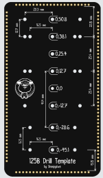
It's important to remember that when you layout the PCB, pads for the potentiometers will be 16mm below where you want the shaft. (Where you want the shaft. Naughty). Let's look at an example. We'll have a row of pots at +38.1mm, +12.7mm, and the LED at -12.7mm:
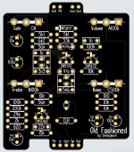
So now, let's create a faceplate. Let's start with the edge cuts and graphics layer already there. I have added an 'x' to show where the LED will be.

To let the LED shine through, we need to have:
- No copper layer.
- Remove the front and back mask.
Important to note that I am exporting a footprint in the F.Mask layer.

Opening KiCad's footprint editor, I import the footprint:

I also want the same for the back mask, so I duplicate the footprint, go "Edit > Edit Text & Graphics Properties", select "Graphic items" as the scope, and change the layer to "B.Mask". Apply and close:
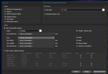
Yay, back mask!

Now add them to the PCB in the same location..
