Basic Schematic Question - Shika

cooltapes

New member
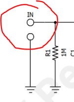
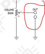
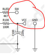
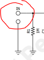
Hi guys, I'm a beginner starting out learning circuits, and I'm trying to duplicate the Shika circuit in kicad.

There's three spots with these double circles leading to ground. It looks like the in/out circles are on most schematics, and the SW/GND circles seem to be the footswitch?

What's going on here? Are these different pins on the foot switch or something?


1785884156914.png 1785884168666.png
1785884130589.png
 

Attachments

  • 1785884145899.png
    1785884145899.png
    21.3 KB · Views: 0
Hi guys, I'm a beginner starting out learning circuits, and I'm trying to duplicate the Shika circuit in kicad.

There's three spots with these double circles leading to ground. It looks like the in/out circles are on most schematics, and the SW/GND circles seem to be the footswitch?

What's going on here? Are these different pins on the foot switch or something?


View attachment 122034View attachment 122035
View attachment 122031
Those are pads for wiring to external input and output jacks, or alternatively to a footswitch.
 
Thank you. But why are they all doubled with another circle headed to ground?
The jacks have to be grounded too, and if you choose to use shielded leads it’s convenient to tie the shield ground right there. But you can do it many other ways if doing your own layout.
 
Technically the switch is omitted for the in/out on the schematic. The in pictured is the circuit in (generally for us coming from the foot switch) but if you omitted the switch it could be read literally as tip = in/out signal and the shaft to ground). Switch (SW) for the ppcb stuff is the LED/CLR portion of the circuit. Some makers leave this off their boards and you're expected to know how to wire a 3PDT switch with the LED block off board. These are included because they are indeed part of the board. They do not affect the sound.
 
Back
Top