Bathtub Reverb Accu-Bell Effector Upgrade Project

SamuelG

Member
This is my project thread to invite comments / mockery *cough* shared laughter or any input readers might deem worth while :cool:
Here is my draft graphic of the Effector against the Reverb
2025-06 AB Effector.png .png.png
I have yet to label the three way switch at top left. It will be up-Reverb, mid-Delay, down-Chorus.
The labelled switch second top left, is the voicing switch similar to the Mod I built from TassiVicking's idea.
There will also be another momentary footswitch in the bottom left corner for the tap-tempo.

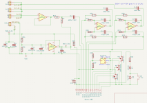
I have based the circuit from the ABE data-sheet example and borrowed ideas from the GT-Stasis Lead Build. Schematic attached.

Thoughts? Ideas for a better name?
 

Attachments

I would just try to wire the Effector module to the same place that the BTDR2 module was connected to, and hope I don't see any magic smoke.
I would change the L7805 to a L7806 and use that for powering the ABE, just connect the In, out1+, out2+, +6V and ground at the terminals for the BTDR2 module.

I would hope that the circuit would be ok for an ABT since it works with the BTDR2 module, you could always run some tests first if you are worried.
I would not add any opamps if it really don't need any.

Place the Tap LED right above the tap switch or to the right of it, unless you want to see it when you tap the switch with your foot.

I might have to try this myself so I get another chorus pedal, one with tubes in it.
The Bath Tub Reverb PCB is the only one I haven't ordered because there is none in stock, all the rest I have or they are on the way right now.
 
Last edited:
I had considered this.
In the end I decided to use this build as a learning experience. I’ve never used op amps before and am enjoying the learning. :)

I know it's expensive, but if I learn how to use the OPA2134 dual op-amp it'll open up more design possibilities for me.

My current inquiry is about signal inversion. I’m trying to find out if the differential output is in phase with the input. I don't have a dual input oscilloscope to make a direct test.

I'm playing with the idea (not entirely seriously) of integrating the tap LED in the UV design using basic 1mm light fibres (red dots).
2025-06 AB Effector 3.png
 
Well hells bells SamulG, you really screwed me over with this one, I can't stop thinking about what I could stick in there instead of the BTDR2.
I am really gonna have to do some measuring so I can determine what I can stick in there, I think the first triode stage has a voltage gain of 2.44 and the second triode has a voltage gain of 33.81 unloaded. (7.75dB and 30.58dB)
I guess anything could go in there, auto wah, octaver, analogue chorus...........
And first I have to wait for Nathan to come back from holidays and order some more BTR PCB's.
At least I have a smile on my face while I wait. :):)
Cheers
Mick
 
Are you familiar with the MN taper pots ? they are dual pots where both are at full output at 12 a'clock.
One track starts at 0% and goes to 100% at 12 a'clock and stays at 100% from 12'clock to 5 a'clock.
The other track starts at 100% and stays at 100% till 12 a'clock and then it drops to 0% at 5 a'clock.
They are really good to use as blend pots since you can have the wet signal at 0% at7 a'clock and then go to full output at 12 a'clock and then stay there till 5 a'clock.
Then you have the dry signal starting at 100% at 7 a'clock and stay at 100% till 12 a'clock and then drop to 0% at 5 a'clock.

When you use a normal pot you can never have both the wet and dry signal at 100% output at the same time, with the MN pots you can so they are great for blend or balance pots.

I wonder how that would go in a reverb module, I think I read somewhere you can get some nice effects that way.
I think it was a tremolo effect with just the wet signal, or something like that.

That is whats missing in your circuit, a way to mix the balance of the wet and dry signals, you don't always want them both at 100%.
 
Great call sir!
No I was not aware of these.
So… how much of a change would it be to swap the current mix pot with the MN taper pot? Perhaps a matter of changing the pin configuration? It could be relatively simple!! I’ll have to have a look next time I’ve got a moment…
The Vol pot will still set the over-all output… hmm… Now you’ve got me excited :)
I have a circuit board ready for print with my current set-up but I want to buy a twin trace oscilloscope and an ABE module to see if it inverts the signal before I order the test boards. I don’t want unintended doppler effects if I can avoid them…
I’m also thinking the plate reverb sound in the ABE might work better than the spring verb I currently have.
Thanks again sir!
 
Think of them as 2 separate volume controls working in opposite directions, except one goes from 0-10 and the other from 10-0.
The difference is that you don't transfer from one pot to the other until they are both at full volume, when one pot goes to full volume the other pot starts to decrease from full volume.
At least one pot is always at full volume, both are at full volume at 12 a'clock.

They work great as a balance pot since both channels are at full volume in the middle (stereos), but they are also great when you want to mix a wet and dry signal together and you are always going to have at least one on all the time.

I think places like the reverb they can be really great but sometimes it is better to just use 2 separate volume pots for the wet and dry signals.
It is a handy little tool to keep in your toolbox when you start making up your own circuits and PCB's.
 
So, after a pause to re-do my Bathtub Reverb MOD, I've now integrated the idea above [thanks Mick].

2025-06 AB Effector 4.png

I have adjusted the circuit so the HPF only impacts the Wet signal path while preserving the Dry path. I've also taken the Mix option away so it can be 0-100% Wet independantly of 0-100% Dry. In order to keep the workable range suitable for different contexts I've added an Attenuation switch.
I think I need to re-assess the Fc options as the Reverb [and possibly the Chorus] will require much higher values. Hmm...
Any thoughts as to what Fc values a bass Chorus could use for clarity?
 
A little something I've ordered. Fingers crossed!
The three pots and the switch give a strong fix to the enclosure. [Back]
I've added further filtering caps for the 9V supply [Front bottom left].
I've used one op-amp as a buffer for the input, another op-amp to buffer the 4.5V rail, and the other two as differential amps for each output of the Accutronics Beltron Accu-Bell Effector module.
I'll use shielded cable for all input/outputs and ground them to this board which will then go to the supply ground at the pedal DC plug.
I did try this build with the OPA4134 but the routing was too crowded and this build enabled me to isolate power from signal better.
I'm much happier that this mod does not interact with the high volts in the BTR board [unlike my bassdude mod].
Front
Vs1 Front.png

And Back
Vs1 Back.png
Here is the schematic for the ABE board.
1757659634325.png

These are the mods for the BTR part. You'll note the different Fc settings. I've tried to use a range of Fc's to cover both Reverb, Chorus, and Echo.
1757659500487.png
The Dry pot will be a right angle pot so it can go where the volue pot sits in the BTR board. The gaps created will alow me to patch in my attenuation switch
As I'm planning on using light tubes to create a halo effect I'm not sure if I'll mount the source LED directly to the board or have it connect via a 1x02 socket.
I'm also using the 100nF 400V caps becuase they fit and are easier to get than smaller value caps at +400V.

And yes... I know this is overkill. But, hey, hopefully I'm learning and this could be the base for who knows what other Fx modules :)
 

Attachments

  • 1757659544971.png
    1757659544971.png
    133.9 KB · Views: 6
Guess what arrived in the mail today...
Still waiting on the PCB... might be lost in mail, so new ones ordered
Other electronic parts are in.
Hoping my enclosure draft 01 works: drilled and waiting for powder coat at Tayda.
and...
A little excited!

IMG_8179.jpg
 
But... I found two errors on my board... I'm not even sure how it happened. Check out the trace running through the Tone leg mount next to R9 and that pot's centre pin. Sigh. I'll have to work out why KiCad let me do that.
 
Last edited:
You should be able to cut those traces with a sharp blade and then just run a small wire linking R14 to R15, not a big problem for one of your first boards.
I think I have done a lot worse over the years, I keep forgetting to let KiCad run an error check sometimes and I miss some of those things as well.
If you cut the traces and link the legs of the resistors before you cut them you wont need a wire link at all.
What is the second fault you found ??
 
Yeah, I’m planning on using some enamelled wire for that.
Front view, top pot, trace running through middle pin.
Back view, top pot, trace running through square pin rather than going around it.
Easy fixes but I was trying hard to avoid that.
 
I think I worked out why it let you run traces through the mounting pads, in your schematic the pots don't have the mounting pad showing so you have not been able to attach the mounting pads to the ground plane.
I think there is a symbol for the pots with mounting pads in the schematic editor but I don't think the footprint has the mounting pad marked as MP so the schematic can't link up with the mounting pads and connect them to the ground circuit.
From memory I opened the 9mm pot footprint up in the footprint editor, renamed the mounting pads to MP and then saved the footprint in another folder.
If the mounting pads were assigned to the ground KiCad would not allow you to run traces through the mounting pads.
That was clear as mud, good luck with trying to fix it.

Cheers
Mick
 

Attachments

  • Pot symbol and footprint.png
    Pot symbol and footprint.png
    376.5 KB · Views: 5
Last edited:
Nice work sir!
I’ll have a look. I’ve since updated KiCad and now none of my traces are tracking properly as well. When I get a chance I’ll have another look. 😎
 
Back
Top