This was a satisfying project for me. I don't often trace pedals, and I don't consider it my strong point, but I took my time on this one.
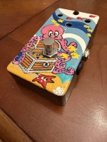
I've been interested in trying a MGMV for years. Like many BJF pedals, the reviews online are glowing and seem magical. And for my part I'm pretty much bought in, I love both the Honey Bee OD and the Deep Blue Delay clones I've made. So I finally found a used MGMV to try, without really intending at first to trace it. It happened to be a hand-painted octopus enclosure... that's all I could find available for sale at the time.
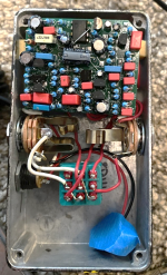
I noticed right away that it sounded like a harmonic tremolo, albeit a uniqe sounding one. There's an FSB thread (some pictures and component labels, no schematic), but I couldn't figure how a 6 Jfets and 1 opamp circuit would be configured for H trem. So I started poking around and couldn't stop. The board was so compact with all the standing resistors so I couldn't see the traces without removing the parts, and I eneded up removing every single component. (A better tracer probably could have kept it in tact).
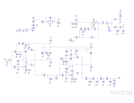
I drew out the circuit and still couldn't really make sense of how it worked. I planned to try my own build to verify the trace but put it aside for a while. Eventually I realized that it's following the Fender Brownface harmonic tremolo schematic (ex 6G5-A), replacing tubes with JFets. But there's 2 harmonic tremolo blocks instead of 1 in the amps. This seemed pretty cool and got me motivated to get pcbs made and build it.
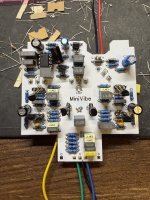
At first go, it sounded really trebley, to the point I thought something must be wrong with my trace or my build. Then I started swapping around my jfets and with the right configuration it sounds perfect, so I guess it's sensitive to matching the jfets. The original was all 2n5952, so far I used all 2n5457 (the pinout is reversed, which I applied). I may try to pull out the original jfets and install to see if there's much noticeable difference.
It really is a great sounding pedal, more vibe-y than my beloved Cardinal V2 harmonic trem (design by jon patton), probably because of the 2 stages. I will be boxing it up soon.
R44 is appears to be a fake-out resistor to thwart would-be tracers such as myself... I hope at this point, long after the pedal is out of production, that BJF would take my endeavor as a compliment.
I've been interested in trying a MGMV for years. Like many BJF pedals, the reviews online are glowing and seem magical. And for my part I'm pretty much bought in, I love both the Honey Bee OD and the Deep Blue Delay clones I've made. So I finally found a used MGMV to try, without really intending at first to trace it. It happened to be a hand-painted octopus enclosure... that's all I could find available for sale at the time.
I noticed right away that it sounded like a harmonic tremolo, albeit a uniqe sounding one. There's an FSB thread (some pictures and component labels, no schematic), but I couldn't figure how a 6 Jfets and 1 opamp circuit would be configured for H trem. So I started poking around and couldn't stop. The board was so compact with all the standing resistors so I couldn't see the traces without removing the parts, and I eneded up removing every single component. (A better tracer probably could have kept it in tact).
I drew out the circuit and still couldn't really make sense of how it worked. I planned to try my own build to verify the trace but put it aside for a while. Eventually I realized that it's following the Fender Brownface harmonic tremolo schematic (ex 6G5-A), replacing tubes with JFets. But there's 2 harmonic tremolo blocks instead of 1 in the amps. This seemed pretty cool and got me motivated to get pcbs made and build it.
At first go, it sounded really trebley, to the point I thought something must be wrong with my trace or my build. Then I started swapping around my jfets and with the right configuration it sounds perfect, so I guess it's sensitive to matching the jfets. The original was all 2n5952, so far I used all 2n5457 (the pinout is reversed, which I applied). I may try to pull out the original jfets and install to see if there's much noticeable difference.
It really is a great sounding pedal, more vibe-y than my beloved Cardinal V2 harmonic trem (design by jon patton), probably because of the 2 stages. I will be boxing it up soon.
R44 is appears to be a fake-out resistor to thwart would-be tracers such as myself... I hope at this point, long after the pedal is out of production, that BJF would take my endeavor as a compliment.