Svenson007
Active member
Hey guys!
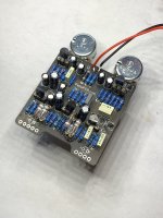
So the Blender (fender blender) is one of my favourite builds lately. I have another completed circuit (in the pic below.)
But it always makes me nervous to drill an enclosure and do all the wiring hoping it works. I had one fail recently, and that was a huge letdown for me. I have somebody Im building this one for. I’ve had mostly success.
I’m always big on testing with other circuits. I just simply take a bunch of alligator clip wires, and strip one end. I just twist the wire on one end so it can be inserted into the input/output, and use the alligator clips for the input and output jacks. Then clip the from the jacks for grounding on a 9v battery.
Some day I’ll build a testing rig. But for now I use my limited time to build pedals, and this method of testing is pretty basic, but works just fine.
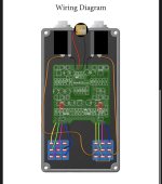
I can’t figure out how to test this type of wiring though (pic below) I like building the Twill deluxe as well with the same wiring…. But don’t feel I need to test that one. It is pretty hard to screw that one up with the minimal part count. I’m not sure how to test klons either.
Does anyone know a way to go about testing this type of wiring? It’s a little foggy because it was last week. But I tried to come up with a way to test a blender…. But I just can think of how.
I did try to find an in and out just to get anything out of it. I have one of those pens from Germany that inject a signal and one wire is attached to the out etc… then you use the pen to find where their is trouble.
When I inject sound straight into the input (with the pedal receiving voltage) it does beep it’s was through. But that doesn’t always guarantee the build is all good.
Sorry this is a long one. But I’m desperately trying to find a way using this style wiring to test properly ( or not properly if it works haha.
Cheers, thanks for reading this.
So the Blender (fender blender) is one of my favourite builds lately. I have another completed circuit (in the pic below.)
But it always makes me nervous to drill an enclosure and do all the wiring hoping it works. I had one fail recently, and that was a huge letdown for me. I have somebody Im building this one for. I’ve had mostly success.
I’m always big on testing with other circuits. I just simply take a bunch of alligator clip wires, and strip one end. I just twist the wire on one end so it can be inserted into the input/output, and use the alligator clips for the input and output jacks. Then clip the from the jacks for grounding on a 9v battery.
Some day I’ll build a testing rig. But for now I use my limited time to build pedals, and this method of testing is pretty basic, but works just fine.
I can’t figure out how to test this type of wiring though (pic below) I like building the Twill deluxe as well with the same wiring…. But don’t feel I need to test that one. It is pretty hard to screw that one up with the minimal part count. I’m not sure how to test klons either.
Does anyone know a way to go about testing this type of wiring? It’s a little foggy because it was last week. But I tried to come up with a way to test a blender…. But I just can think of how.
I did try to find an in and out just to get anything out of it. I have one of those pens from Germany that inject a signal and one wire is attached to the out etc… then you use the pen to find where their is trouble.
When I inject sound straight into the input (with the pedal receiving voltage) it does beep it’s was through. But that doesn’t always guarantee the build is all good.
Sorry this is a long one. But I’m desperately trying to find a way using this style wiring to test properly ( or not properly if it works haha.
Cheers, thanks for reading this.