Bluesbreaker circuit... Anyone care to check my work?

ChrsGuit

Active member
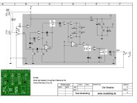
I built a Musikding BB a while back. I absolutely love it... moreso than my ACTUAL mk1 BB reissue...
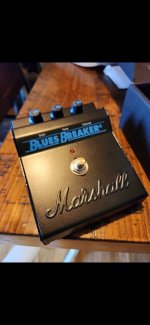
I'd like to build an identical Musikding but using a PedalPCB board, 125b enclosure, etc... Essentially I want to use the PedalPCB board and substitute the Musikding values (photo 2) onto a PedalPCB Bluebreaker board. The MD kit is kind of a pain to fit in a 125b enclosure (due to having to separately wire all the pots and affix the board with cheap adhesive standoffs, etc)... I prefer the more seamless route using PEDALPCB boards and enclosure templates.
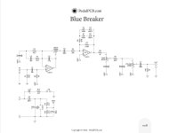
Anyway, the circuits are identical but the components are not labeled the same nor values 100% part for part...
I transposed the different values to the Pedalpcb layout as such:
Change
R1 to a 1m, not 2m2
C5 to a 220n, not 100n
R5 to a 3.3k, not 10k
D1-D4 to 1n4148s not 1N914s
D5 is a 1N4001 (but wont matter if it stays a 5817... just a protection diode)
and the rest of the circuit remains the same...

I'm fairly certain (looking at the schematics) that I have got everything but I wanted to be certain, so if anyone sees a mistake or something I missed, chime in
Many thanks!
 

Attachments

  • Screenshot_20230826_202359_Acrobat for Samsung.jpg
    Screenshot_20230826_202359_Acrobat for Samsung.jpg
    81.8 KB · Views: 42
  • Screenshot_20230826_202332_Acrobat for Samsung.jpg
    Screenshot_20230826_202332_Acrobat for Samsung.jpg
    166.9 KB · Views: 42
Last edited:
I think 1N914 and 1N4148 are perfect substitutes for each other, they do the exact same thing.

You can use 1M for R1, if the footswitch do some popping noise on activation, try 2.2M, or increase the led resistor (R13 on PPCB schematics) value up to 10 or 20k.

C5 and R5, i would put both values on some SPDT toggleswitch, and see which ones sound best. In fact, i would probably keep the toggle to have both settings available, if changing values does any difference at all...
Oh, I certainly know the Musikding circuit sounds good... But I have it in a big, ugly 1590bb enclosure and it's kind of a cheap kit... I want to build one nice and tidy using the Pedalpcb board but installing all values from the musikding version (they are different). I just wanted to be sure
 

Attachments

  • Screenshot_20230828_000100_Instagram.jpg
    Screenshot_20230828_000100_Instagram.jpg
    578.8 KB · Views: 4
Have you tried some Morning Glory clone ?

Do you prefer the original Blues Breaker circuit over the Morning Glory ?
Yeah, I built one... didn't like it... just too much harsh treble... like a Klon has. I tried adjusting some values and it improved a bit, but I just don't dig it. It doesn't have the same glassy punch, clarity and nice round bass response that the Musikding does... idk what's with their choice of values but it sounds great... better than the Morning Glory and the mk1 bb reissue I have...
 
It looks like you're lowering the input impedance so it may sound a little warmer. Also changing R5 to 3.3k is going to give you about three times as much maximum gain. That's the first time I've seen a bluesbreaker circuit with that value there.

220k/3.3k = 66.6~
220k/10k = 20

Putting a cap in parallel with that 220k resistor can tame some of the brightness. Might want to try a 220pf up to a 470pf. I think the bright switch on the Morning Glory is 470pf, but I can't remember for sure off hand.
lol, I certainly appreciate it, but there has been a bit of a misunderstanding. I posted two photos of schematics above. I'm just wanting to use a PedalPCB BB board (photo 1) to make the exact same pedal in the Musikding "Der Breaker) schematic (photo 2).
I've already built the Musikding version... I love the way it sounds... When I shot it out against a legit Marshall Bluesbreaker and a Morning Glory, took them off the board and kept the Musikding on there...

I'm just trying to transpose the Musikding values onto the Pedalpcb Breaker board and wanted to be sure I have everything correct
 
It looks like you're lowering the input impedance so it may sound a little warmer. Also changing R5 to 3.3k is going to give you about three times as much maximum gain. That's the first time I've seen a bluesbreaker circuit with that value there.

220k/3.3k = 66.6~
220k/10k = 20

Putting a cap in parallel with that 220k resistor can tame some of the brightness. Might want to try a 220pf up to a 470pf. I think the bright switch on the Morning Glory is 470pf, but I can't remember for sure off hand.
side note, good idea on taming the brightness... on the Musikding pedal, I have to run the tone about 9.5-10 o'clock. it'd be nice to have an equal amount of sweep each way
 
Yeah, I built one... didn't like it... just too much harsh treble... like a Klon has. I tried adjusting some values and it improved a bit, but I just don't dig it. It doesn't have the same glassy punch, clarity and nice round bass response that the Musikding does... idk what's with their choice of values but it sounds great... better than the Morning Glory and the mk1 bb reissue I have...
Sorry if i am going a bit off-topic :

I guess it depends on the version of your build : a straight clone (PPCB style), or some ultra modded version of the circuit, designed to get more adjustability than the original, and emulate all the most interesting variants.

The second possibility always seem more interesting to me, you just have to add some toggleswitches on one build, instead of building all the various versions.

I can recommend this project :


It's a Blues Breaker circuit compatible with AnalogMan King of Tone, Morning Glory and Blues Breaker values. There are 4 toggleswitches allowing to calibrate the circuit in order to get different things from clean driver to powerful overdrive with various flavors. One toggle allows to select between 3 capacitors, to get a different bass response and presence.
There's also a Presence trimmer, that is very useful as an external control, wired to a pot.

Unfortunately, Delyk's website is currently shut down, you can still order some boards at musikding, i can provide the v.2 BOM, schematics and instructions if necessary. Delyk had to mail it to me, because it was (and it's still) unavailable online.

Should be easier to mod your own Morning Glory clone, especially if you don't really like it. You can at least fix the bass cut quite easily.


Back
Top