Buffer for muzzle - where to input?

zeropluszero

Well-known member
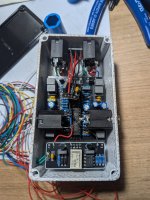
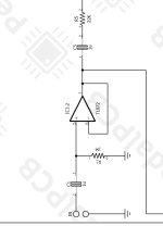
36376.png 36379.jpg

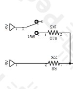
This is potentially more of a sanity check than anything else. I'm building a muzzle, and I'm using a basic relay, as well as a simple jfet buffer for what I hope is the input. I heard this circuit likes a buffered input so I figured internally would be good.
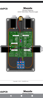
It's just occurred to me that the input for this circuit is actually the side Jack if I'm planning to use this in 4 cable method..so the buffer on the input needs to be between the side chain input and the relay, do I have that right?
And if I took it out of 4cable, say if I wanted to just use two cables, I would use the top jacks, and I would in this case lose the buffer, which I'm sure is fine. Or would I use the two side jacks and not the top jacks?

I should probably get some sleep.
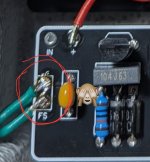
Just so everyone knows, it's smart to attach the footswitch to the relay before you solder the relay board to the PCB using resistor wires. If I haven't broken a connection on this project, between the offboard switch, relocated led and this other stuff I'm jamming in it it will be a miracle.
 
Someone correct me if I’m wrong here but technically I believe the muzzle already has an input buffer
IMG_2644.jpeg
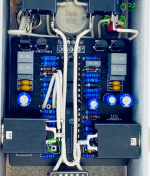
and that “feeds” a “buffered” signal to the key when side chain isn’t used, so I think you could put a buffer on the key/ side chain input but I have no Idea how that will interact with the circuit when the side chain isn’t in use. And a buffer would probably only be relevant on the key input if it only sees a signal directly from the guitar without any other circuits in between or a long cable run. At least that’s how I understand it. One concern I would have (probably just being extra paranoid here) is you are not filtering the power to that buffer you are just tapping the 9v jack, Worse case scenario you cook the 4301and that’s a bad day right there.

It’s probably a reasonable gamble but for what it’s worth in my opinion you are gambling with an expensive hard to find IC if it’s a real 4301. Which at first glance appears to be. (Good find!)
 
I had also suspected that there would already be a buffer....sorry my schematic reading isn't good enough to recognise one when I see it.

Even better I'll just pull it entirely. 👍
 
I didn't want to build the muzzle unless I could find the chip and it had been out of stock for this site for months. Found one and ordered all my parts, by the time the Tayda order rocked up this week, Robert had the retrofit back in stock 🥲
 
ok, so after fiddling with this again, i have a new issue, but im hoping this one isnt too hard.
I've got the muzzle working after sorting out a wiring issue, I had thought that the switched tip was going to ground on the jack, but its to a different pin - fixed that, and now the gate is gating in 4cable and 2cable method - great.
only thing is, the LED is not working when the gate is gating - and when the LED is lit, the effect appears to be off - surely some sort of switching issue, maybe because I have the relay bypass in there?
when the LED is lit - if i play the light changes from red to green and when i stop it goes to red again - so its reading from the input, its just reversed, since the effect isnt working when the LED is also lit.
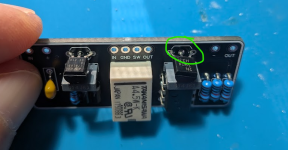
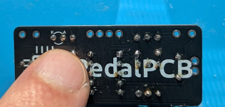
do I need to connect the LED to the bypass somewhere? I note the bypass module has A & K markers on the back of the transistor?
1759041346983.png 1759041365220.png
 
Have you tried jumping the pads on the muzzle pcb to bypass the switch entirely ( like you would for testing and verification of the circuit out of the enclosure before you did any off board wiring? I would verify the circuit is operating as designed before worrying about the relay board. If the circuit operates as designed then start looking at the relay board and how you have it connected.
 
Last edited:
The circuit is working as designed, it's just the led which I would usually use to indicate whether the effect is on or off, is on when the effect is off, and off when the effect is working.

When the effect is off, the led is on and red when I am not playing, and green when I am, as I would expect...if the effect was on
 
Unless I completely misunderstand how this is wired up, you're missing the Input / Output connections to the relay bypass module.

Right now it's turning on the LED when active and grounding the IN pad when bypassed, but it's not feeding any signal into the IN pad of the Muzzle.

So what I suspect is happening is that your effect is actually active when you're calling it bypassed, but it's behaving bypassed because it has no input signal (by way of the Relay Bypass module).
 
36549.jpg

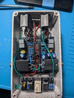
Oh, the input was connected, just not in my initial photos. Here is how it is currently wired up, green between lower jacks tip to tip, and then blue off this to the T on the board.
The switched tip is to the outer connection on the board and I have a ground to the middle at the moment.
Do I need to connect the relay board to the sidechain jacks for input/output instead?
 
My recommendation still stands remove the boards from the enclosure and test them separately to verify they operate as designed one of them isn’t working properly and this narrows it down which one to troubleshoot, with them removed you have access to both sides of the boards.
 
@Paradox916 have I got that range switch soldered incorrectly?
I have all three points on the PCB attached to each pin of an on-on switch - if I check your build pic - which is obviously a heavy influence - I think you've only connected two maybe?
1759214976680.png
I've pulled it from the enclosure and now the sound is worse than ever, Ive removed the relay and will test that again shortly.
 
Ok, pulled it all apart, and I have it working without the relay. I definitely needed a ground connection between the two middle jacks, but I'm pretty sure I had that before as well. Gate is working and the light is working right now.
I tested the range switch pulled off and put back on again and it also is working with the on-on switch so that wasn't the issue either.

...Had a 3906 instead of 3904 🙄
 
Last edited:
Relay working after changing out the transistor and going over it again to make sure everything was connected.
Now I have to fit this rats nest back into the box

-I think the issue is that it needed a ground connection between the two lower jacks & or that the wrong transistor on the relay board was the issue here.

36591.jpg
 
@Paradox916 have I got that range switch soldered incorrectly?
I have all three points on the PCB attached to each pin of an on-on switch - if I check your build pic - which is obviously a heavy influence - I think you've only connected two maybe?
View attachment 103704
I've pulled it from the enclosure and now the sound is worse than ever, Ive removed the relay and will test that again shortly.
IMG_2652.jpeg
Pad 1 of the range switch doesn’t go anywhere so it’s technically not needed other than to accommodate the called out micro switch if it is modded for an external range switch you only need to wire up 2 and 3. Glad you got it working. Good job!
 
Back
Top