Hi all first post...
I'm still very much new to building and still at the paint by numbers, fill out a PCB and solder stage.
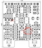
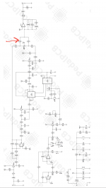
I've ended up lifting the square pad from the blend pot on the back of the PCB, looking at the schematic I think I could put a jumper in to the 12k resistor at R36, I'm not sure which leg though.
Could anyone help me out and confirm that a jumper to R36 is correct and which leg on the actual PCB to go to please?
Thanks in advance!


