- Build Rating
- 5.00 star(s)
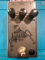
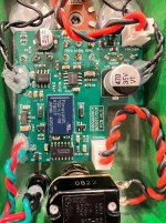
Here's my latest spin of the Catalinbread Varioboost circuit. My gateway to this circuit was the PedalPCB Mercurial Boost. I then made my own custom PCB of the circuit, with integrated relay bypass, and all three knobs on the same horizontal line.
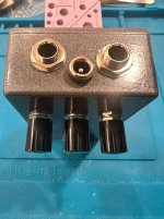
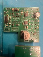
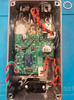
Now I took it a step further and shrunk it down by going with a surface-mount design. This allowed me to fit the circuit into a 1590B enclosure with top-mount jacks. Credit to @MichaelW for his 1590B Top Mounted Jacks Guide. (Only when I took the picture did I realize my I/O jacks aren't straight!)
Not a lot to say about this circuit that hasn't already been said. It's kinda-sorta a one-band parametric EQ. It's a very swiss-army-knife kind of pedal. I use it as a lead boost.
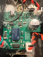
I had JLCPCB fabricate the board and do the SMD assembly. Everything worked on first power-up! My only build issue was that I habitually use pre-cut lengths of wire for going between the I/O jacks and the PCB. And the wires I used were just a wee bit too short. And of course I realized this after I put a blob of hot-melt glue where the wires mate to the PCB. So I had to splice a length of wire in. Easy but tedious fix.
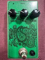
The enclosure is one of my favorites, "Weston Grey" from @StompBoxParts (link). The graphics are Sunnyscopa film-free waterslide decal. This time around, I had pretty much perfect transfer of the toner. I did pre-wipe the enclosure with acetone before applying the decal. The graphic is the "Guardian" from Zelda. I've used this before, I think it looks great on the Weston Grey. I've sold all my previous pedals that used this graphic, and this Varioboost I plan on keeping!
I have a few spares of the assembled SMD PCBs, if anyone is interested in one, PM me.
Now I took it a step further and shrunk it down by going with a surface-mount design. This allowed me to fit the circuit into a 1590B enclosure with top-mount jacks. Credit to @MichaelW for his 1590B Top Mounted Jacks Guide. (Only when I took the picture did I realize my I/O jacks aren't straight!)
Not a lot to say about this circuit that hasn't already been said. It's kinda-sorta a one-band parametric EQ. It's a very swiss-army-knife kind of pedal. I use it as a lead boost.
I had JLCPCB fabricate the board and do the SMD assembly. Everything worked on first power-up! My only build issue was that I habitually use pre-cut lengths of wire for going between the I/O jacks and the PCB. And the wires I used were just a wee bit too short. And of course I realized this after I put a blob of hot-melt glue where the wires mate to the PCB. So I had to splice a length of wire in. Easy but tedious fix.
The enclosure is one of my favorites, "Weston Grey" from @StompBoxParts (link). The graphics are Sunnyscopa film-free waterslide decal. This time around, I had pretty much perfect transfer of the toner. I did pre-wipe the enclosure with acetone before applying the decal. The graphic is the "Guardian" from Zelda. I've used this before, I think it looks great on the Weston Grey. I've sold all my previous pedals that used this graphic, and this Varioboost I plan on keeping!
I have a few spares of the assembled SMD PCBs, if anyone is interested in one, PM me.