
bretvh
Member
So I bought this board a long time ago and finally got around to building it. Having an issue with extremely low output. I can barely hear the modulation effects, and the guitar is indeed distorted, but super quiet. Volume knob doesn't really have any effect on the loudness.
Here is everything I have tried:
- Swapped the PT2399 and LM386 chips a few times
- Verified the PT2399 and LM386 are getting proper voltages
- Cleaned up and reflowed all joints
- Checked resistor and cap values
- Checked wiring
- Checked for solder bridges
- Traced the circuit with a test probe
- The LED does react to the guitar input and the tracking knob does have an effect on it
What I have found is that the sound level is dropping somewhere between R2 and R7/8. I barely get any tone going into the PT2399 on pin 16. If I jumper across from R2 to R7, I get full volume.
The only thing between those Resistors is a trace. Nothing looks damaged on the PCB.
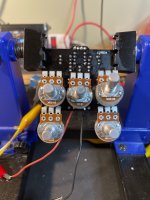
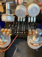
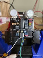
So, this leads me to think that maybe something else later or earlier in the circuit has an issue. I've added a few photos. It looks a little messy because I reflowed everything and scraped gently between the solder pads to ensure no bridges were afoot.
Note that R3 and R9 were replaced with the proper values (I think I somehow managed to put 75k in those spots. I don't even know how...). The other ones look correct to me, but I am also not even close to being adept at deciphering color codes on these things.
Does anyone have any ideas on this one? I thought, "Oh, this will be an easy build!" I mean, I'm not a total newb and I just built two General Tso's compressors over the weekend, which worked first try! Unfortunately, this one has me stumped and I am sure there is something simple I am overlooking.
Thanks in advance for any help!
Here is everything I have tried:
- Swapped the PT2399 and LM386 chips a few times
- Verified the PT2399 and LM386 are getting proper voltages
- Cleaned up and reflowed all joints
- Checked resistor and cap values
- Checked wiring
- Checked for solder bridges
- Traced the circuit with a test probe
- The LED does react to the guitar input and the tracking knob does have an effect on it
What I have found is that the sound level is dropping somewhere between R2 and R7/8. I barely get any tone going into the PT2399 on pin 16. If I jumper across from R2 to R7, I get full volume.
The only thing between those Resistors is a trace. Nothing looks damaged on the PCB.
So, this leads me to think that maybe something else later or earlier in the circuit has an issue. I've added a few photos. It looks a little messy because I reflowed everything and scraped gently between the solder pads to ensure no bridges were afoot.
Note that R3 and R9 were replaced with the proper values (I think I somehow managed to put 75k in those spots. I don't even know how...). The other ones look correct to me, but I am also not even close to being adept at deciphering color codes on these things.
Does anyone have any ideas on this one? I thought, "Oh, this will be an easy build!" I mean, I'm not a total newb and I just built two General Tso's compressors over the weekend, which worked first try! Unfortunately, this one has me stumped and I am sure there is something simple I am overlooking.
Thanks in advance for any help!
 I guess that's what I get for rushing. I will get them cleaned up and see if that helps. Barring that, any other ideas?