Cobalt Drive Not Working

Forjo

New member
My Cobalt Drive build is not working. Sound is fine if board is not engaged. No sound if I engage the board. I'm following another thread in which builder has the same problem and trying suggestions. I was wondering if someone could provide me with the voltages on the IC, transistors and JFETs? My issue is that I am getting continuity where required, but no audio (using function generator, DMM, transistor checker, and audio tracer).
Thanks in advance!
 
Solution
If you’re using an audio probe, follow the audio path (ref the schematic) and find where the audio drops out. That’ll help narrow your focus. Beyond that, clear pictures will be help move things along.

EDIT: Aren’t voltage posted in the other thread?

My Cobalt Drive build is not working. Sound is fine if board is not engaged. No sound if I engage the board. I'm following another thread in which builder has the same problem and trying suggestions. I was wondering if someone could provide me with the voltages on the IC, transistors and JFETs? My issue is that I am getting continuity where required, but no audio (using function generator, DMM, transistor checker, and audio tracer).
Thanks in advance!

My Cobalt Drive...
If you’re using an audio probe, follow the audio path (ref the schematic) and find where the audio drops out. That’ll help narrow your focus. Beyond that, clear pictures will be help move things along.

EDIT: Aren’t voltage posted in the other thread?
 
If you’re using an audio probe, follow the audio path (ref the schematic) and find where the audio drops out. That’ll help narrow your focus. Beyond that, clear pictures will be help move things along.

EDIT: Aren’t voltage posted in the other thread?

My Cobalt Drive build is not working. Sound is fine if board is not engaged. No sound if I engage the board. I'm following another thread in which builder has the same problem and trying suggestions. I was wondering if someone could provide me with the voltages on the IC, transistors and JFETs? My issue is that I am getting continuity where required, but no audio (using function generator, DMM, transistor checker, and audio tracer).
Thanks in advance!
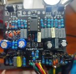
Pictures!
 
Solution
Clean the board, get rid of all of the flux residue.
Where did you get the J201s?
Did you sub any parts?
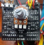
Where is the GAIN pot? Is it wired correctly?
How are you applying power to the board? The power pads have no wires in them. Look at page 4 of the Build Docs.
Does the LED light up?
R4 looks like it might be damaged.
Looks like some of the resistor leads could be contacting the leads on Q6 or Q7.
With power on and no signal, Q5-C, Q6-C & IC1-6 should be close to +4.5V.
Depending on the readings, we'll proceed from there.

Is this your first build? You should be using 1/8W resistors, they'd fit better.
 
Board was cleaned w Iso Alcohol, I'll redo it. The gain pot is not RA pcb Mt. I wired in a non pcb dual correctly.
The JFETs currently in the board are 2N5457. Using them for testing until Sot J201s arrive. I took out the J201s and ordered sot versions from 3 different suppliers including PedalPCB. Just learned that Taydas pinout on Sot to thruhole doesn't match OnSemi mmbf201 pinout.
The board is being powered by a test jig. Have built around 20 pedals, this is the first one that has stumped me. Thanks for the info on 1/8 watt. I just ordered a kit of them. This is the first board I've ordered that uses 1/8w resistors. I will get back to you on results of your guidance. Thks.
 
Last edited:
Clean the board, get rid of all of the flux residue.
Where did you get the J201s?
Did you sub any parts?
Where is the GAIN pot? Is it wired correctly?
How are you applying power to the board? The power pads have no wires in them. Look at page 4 of the Build Docs.
Does the LED light up?
R4 looks like it might be damaged.
Looks like some of the resistor leads could be contacting the leads on Q6 or Q7.
With power on and no signal, Q5-C, Q6-C & IC1-6 should be close to +4.5V.
Depending on the readings, we'll proceed from there.

Is this your first build? You should be using 1/8W resistors, they'd fit better.
 
There are no wires connecting to the + and - power pads on the board. Looks like you are hooking power up to the LED pads. That's what I meant when I asked how power is getting to the board. It might be getting there, but not to the right place. Look at page 1 of the Build Docs. Check the wiring.
 
Success! I incorrectly thought that the Swc input turned on and off the 9v. Lesson learned and I profusely thank you. Glad it didn't take 22 pages this time! Next project Pitch Witch w 1/8w resistors!
 
Unbelievable, I ordered MMBFJ201. The bag is labelled MMBF0201. I'll delete previous post. Guess I'll have to wait for my MMBFJ201s from PedalPCB. Remind me to never build anything with J201s in them. So far I received fake parts from 2 suppliers and the wrong parts from another.
 
Last edited:
Back
Top