analog_bham
Well-known member
Not sure if this is the right place for this...
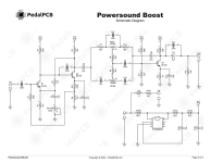
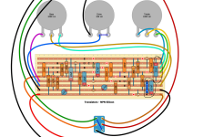
I am using the layout below for a Colorsound Power Boost and using the values from the PedalPCB Powersound Boost as a reference. In the layout, the 22uf electrolytic on the far right corresponds to C8 in the schematic for the Powersound Boost, but the layout appears to have the direction of the cap backwards. I was wondering if I'm correct that the cap should be reversed. The way that it looks to me, the signal is coming out of the tone circuit, entering 22u from the negative side in the layout and then going to the positive side of the 4u7.
I also changed the 3k9 at R13 to the 1k8 in the schematic and also added the 220n c13 parallel cap just to the left of the bottom right 4u7 electrolytic.
I have a terrible time with stripboard layouts and would appreciate help "checking my work."
Thanks!!
John