analog_bham
Well-known member
- Build Rating
- 5.00 star(s)
I've been in a deep Big Muff rabbit hole lately and came across the Colorsound Power Boost when reading about David Gilmour's use of the Muff. I pulled up the PPCB schematic and figured I would breadboard it to give it a try. I ended up liking it enough to try my hand at a stripboard layout of it today.
I have a love/hate relationship with stripboard. It looks great to me, but I swear I can't seem to get one to work to save my life. Undaunted, I decided to give this one a try today.
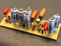
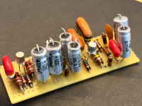
I had to adjust a few values for parts on hand, including 5uf and 20uf electrolytics instead of 4u7 and 22. Some resistors were changed, but given that they were carbon comps, I found ones that were at least within tolerance of the original component.
To my surprise, this one worked right out of the gate (after asking some questions here in the stripboard forum). I did take my time and was meticulous about checking and rechecking continuity to ensure there weren't any unintended solder bridges. I triple checked layout of parts and found a couple of things that I had done incorrectly, but found them early so fixing them was easy.
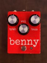
The boxing isn't the neatest. I think that's what I struggle with the most with stripboard/tagboard/turret layouts. The wiring just feels like contained chaos instead of being tidy. I tried out a new paint color for the enclosure. It's a "Fluoro Red" that honestly is awful. It's an Ironlak paint that no matter how long I shook it still came out as a mix of dust and liquid globs. I had to sand it pretty extensively and so the end result is kind of a "relic" type paint job. Last week, I mistakenly ordered these giant Boss knobs. They're absolutely ridiclous but worked out ok on this... 3 knobs down, 12 more to go!!!
Anyway, the pedal actually sounds great. Really pleased with it.
I used BC109c transistors and then the usual litany of my feel-good, aesthetic component choices.
It's definitely worth a go if you haven't played one before. It's a really great boost that then all of the sudden turns into a fuzz pedal.
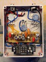
Also, this was my first use of the PPCB charge pump board. Love it!! Running the Power Boost at 18v. I will know next time to solder the electrolytics to the other side of the board though...
This is also my first use of the Lumberg 1/4" jacks. Totally sold on those. They're fantastic!
John
I have a love/hate relationship with stripboard. It looks great to me, but I swear I can't seem to get one to work to save my life. Undaunted, I decided to give this one a try today.
I had to adjust a few values for parts on hand, including 5uf and 20uf electrolytics instead of 4u7 and 22. Some resistors were changed, but given that they were carbon comps, I found ones that were at least within tolerance of the original component.
To my surprise, this one worked right out of the gate (after asking some questions here in the stripboard forum). I did take my time and was meticulous about checking and rechecking continuity to ensure there weren't any unintended solder bridges. I triple checked layout of parts and found a couple of things that I had done incorrectly, but found them early so fixing them was easy.
The boxing isn't the neatest. I think that's what I struggle with the most with stripboard/tagboard/turret layouts. The wiring just feels like contained chaos instead of being tidy. I tried out a new paint color for the enclosure. It's a "Fluoro Red" that honestly is awful. It's an Ironlak paint that no matter how long I shook it still came out as a mix of dust and liquid globs. I had to sand it pretty extensively and so the end result is kind of a "relic" type paint job. Last week, I mistakenly ordered these giant Boss knobs. They're absolutely ridiclous but worked out ok on this... 3 knobs down, 12 more to go!!!
Anyway, the pedal actually sounds great. Really pleased with it.
I used BC109c transistors and then the usual litany of my feel-good, aesthetic component choices.
It's definitely worth a go if you haven't played one before. It's a really great boost that then all of the sudden turns into a fuzz pedal.
Also, this was my first use of the PPCB charge pump board. Love it!! Running the Power Boost at 18v. I will know next time to solder the electrolytics to the other side of the board though...
This is also my first use of the Lumberg 1/4" jacks. Totally sold on those. They're fantastic!
John