Cosmetology (making your pedal pretty)

Mike McLane

Active member
A number of people are playing with means to customize the appearance of their pedals. I have experimented with laser printers and want to set up a 125B template. In looking at some of my builds I come up with the following and want to know if this control/footswitch spacing will apply to all PedalPCB designs. Basically, controls for 2-across designs are spaced 9/16" from center (yes, ".06525" is a typo) and the 3-across are 13/16" from center (using the center line for one of the controls). Top tier of controls is 7/8" from top edge and 2nd tier is 1' below that. Toggle switches would correspond to one of these same intersect points as the PCB design call out. Mr. PedalPCB, please confirm if this works.

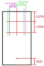
125B Box Template.JPG
 
Last edited:
Usually, but not always. (with a couple corrections, the horizontal spacings are 0.65" and 0.8", not 0.6525" and 0.8125")

The majority of the 125B-sized boards do follow that standard, but a few will stray when required for layout purposes. The one and two knob layouts tend to vary somewhat (vertically) between designs.

It'd be more accurate to measure the distance between the objects (or from the center of the enclosure), rather than from the edges of the enclosure.

For example, there is usually 1" between the first and second row of pots, and 3.275" between the top row of pots and the footswitch. For layouts where the LED is near the bottom, there is usually 0.7" distance between the LED and footswitch. When I create a new drill template the drill marks are always placed relative to one of the existing standards (I usually start with a 6-knob template and modify as needed).

Measurements are always done relative to another drill mark (or the center of the enclosure), never from the edges of the enclosure.


One thing that might help, if you look below the "Add to cart" button on the product pages you'll see Tags. (For example, 3-Knob Type 1 in the pic below). Any PCB with that tag will have the same control layout. You can also click the tag to see other PCBs that use that same layout. These also correspond to the pre-drilled enclosures at Tayda.


1619883956567.png

1-Knob (Type 1)
2-Knob (Type 1)
3-Knob (Type 1)
4-Knob (Type 1)
5-Knob (Type 1)
5-Knob (Type 2)
6-Knob (Type 1)
 
Last edited by a moderator:
Ah Haa! Very enlightening! I know you don't have anything else to do so it would be super slick to put dimensions on the drilling template based on some fixed base point like the "geographic" center of the enclosure. Then all our pedals would not only be purdy, but that would increase the tonal quality of the pedal by at least 20% :unsure:
 
Perhaps easier, if you did these drilling templates in a typical CAD program like AutoCad a DXF save of these files could be pulled into illustration software like Illustrator or Inkscape (freeware). I would hope it would be easy for you to set up a file library on your website for downloads for those of us who want to tinker with graphic designs.
 
Back
Top