owlexifry
Well-known member
i've never built a reverb or a PT2399 based circuit before. this is my first time dipping my toes into this wild territory... built heaps of drives, but nothing fancy like this yet..
the idea behind this build was inspired by howard moon, well, this scene:

i wanted to build a circuit for my friend inside a crab. i was hoping he wanted a distortion or something, but he asked for a reverb
i didn't really want to spend on a belton brick, and I wanted to to give these chips a go, so i thought this 2x PT2399 based circuit would be cool:

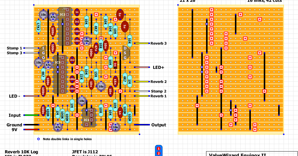
followed this layout:

built it (there's much work to be done yet)


works great with the 'reverb' control turned all the the way down, the dry/clean signal is passing crystal clear, no worries.
but as soon as i turn up the 'reverb' control' there is an awful oscillating low frequency noise, gets louder the more you turn it up. makes no difference whether effect is switched on or bypassed. [and boy howdy that noise - frightened my partner in the other room, thought the aliens were arriving to take us ]
]
voltages looked ok. regulator putting out a healthy 5.02V. (8.99V to the TL072 with my DIY 9V regulated power supply.. full voltage list below).
whipped out the audio probe to trace the signal, not real sure what's happening with this circuit, so i thought i'd see what happens when it goes to the PT2399 ICs, couldn't really find anything profound or indicative of something wrong, except the signal is clear until it passes this 10K resistor:

with the audio probe, before the 10K resistor, signal is clear, once it passes and meets the 15n cap, the oscillating noise is there. not sure if that means anything or is useful.
i bought the PT2399 chips from tayda. reading that these can be hit and miss, i've tried 3 different pairs (from my purchase of x8), but nothing changes.
could the chips, if faulty, be responsible for this noise?
full voltage readings:
IC2
1- 5.02
2- 2.516
3- 0
4- 0
5- 3.016
6- 2.463
7- 2.5 <-> 2.8 (oscillates up and down)
8- 2.5 <-> 2.8 (oscillates up and down)
9- 2.521
10- 2.517
11- 2.517
12- 2.489
13- 2.49
14- 2.498
15- 2.516
16- 2.516
IC3
1- 5.02V
2- 2.51
3- 0
4- 0
5- 2.475
6- 2.331
7- 2.5 <-> 2.8 (oscillates up and down)
8- 2.5 <-> 2.8 (oscillates up and down)
9- 2.513
10- 2.511
11- 2.510
12- 2.517
13- 2.51
14- 2.51
15- 2.509
16- 2.51
IC1
1- 4.49
2- 4.49
3- 4.07
4- 0
5- 4.47
6- 4.51
7- 4.49
8- 8.49
not sure if those pins 7+8 on IC2+3 are supposed to oscillate like that...
i'm stumped at this point and don't really know what else to look for.
i would greatly appreciate some advice with this circuit, i really hope i can get this to work.
thanks")
the idea behind this build was inspired by howard moon, well, this scene:

i wanted to build a circuit for my friend inside a crab. i was hoping he wanted a distortion or something, but he asked for a reverb
i didn't really want to spend on a belton brick, and I wanted to to give these chips a go, so i thought this 2x PT2399 based circuit would be cool:

followed this layout:

built it (there's much work to be done yet)


works great with the 'reverb' control turned all the the way down, the dry/clean signal is passing crystal clear, no worries.
but as soon as i turn up the 'reverb' control' there is an awful oscillating low frequency noise, gets louder the more you turn it up. makes no difference whether effect is switched on or bypassed. [and boy howdy that noise - frightened my partner in the other room, thought the aliens were arriving to take us
]voltages looked ok. regulator putting out a healthy 5.02V. (8.99V to the TL072 with my DIY 9V regulated power supply.. full voltage list below).
whipped out the audio probe to trace the signal, not real sure what's happening with this circuit, so i thought i'd see what happens when it goes to the PT2399 ICs, couldn't really find anything profound or indicative of something wrong, except the signal is clear until it passes this 10K resistor:

with the audio probe, before the 10K resistor, signal is clear, once it passes and meets the 15n cap, the oscillating noise is there. not sure if that means anything or is useful.

i bought the PT2399 chips from tayda. reading that these can be hit and miss, i've tried 3 different pairs (from my purchase of x8), but nothing changes.
could the chips, if faulty, be responsible for this noise?
full voltage readings:
IC2
1- 5.02
2- 2.516
3- 0
4- 0
5- 3.016
6- 2.463
7- 2.5 <-> 2.8 (oscillates up and down)
8- 2.5 <-> 2.8 (oscillates up and down)
9- 2.521
10- 2.517
11- 2.517
12- 2.489
13- 2.49
14- 2.498
15- 2.516
16- 2.516
IC3
1- 5.02V
2- 2.51
3- 0
4- 0
5- 2.475
6- 2.331
7- 2.5 <-> 2.8 (oscillates up and down)
8- 2.5 <-> 2.8 (oscillates up and down)
9- 2.513
10- 2.511
11- 2.510
12- 2.517
13- 2.51
14- 2.51
15- 2.509
16- 2.51
IC1
1- 4.49
2- 4.49
3- 4.07
4- 0
5- 4.47
6- 4.51
7- 4.49
8- 8.49
not sure if those pins 7+8 on IC2+3 are supposed to oscillate like that...
i'm stumped at this point and don't really know what else to look for.
i would greatly appreciate some advice with this circuit, i really hope i can get this to work.
thanks

 many thanks for the tips!
 so stoked.


 VE the
  idea.
idea.


