- Build Rating
- 5.00 star(s)
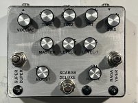
This is a prototype 3-in-1 build for a client (my one and only client). When he engaged me for the phaser build, he was also asking about fitting three circuits into a single enclosure. Ideally he wanted all three in a 125B enclosure, but we settled on a 1590BBS. He's a fan of my soft-touch bypass schemes, so the custom job had to use those.
We went back and forth for a while, brainstorming ideas. He had a rough idea of what he wanted, but a lot of our discussion was him asking how complex various circuits are, and did I think I could fit them all in a relatively compact enclosure. So naturally we had to lean towards simple circuits, just due to available PCB space. What we ended up with is the following, in order from input to output:
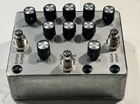
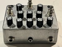
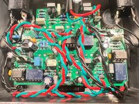
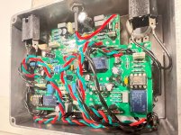
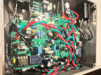
The prototype went together without any major issues, and worked on first power-on! The only real issue was that I drilled the holes for the status LEDs too close to the sides of the enclosure, so didn't have enough room for metal LED bezels. So I had to use some plastic ones. I also ordered a bunch of small knobs, but accidentally specified 6mm diameter instead of 6.35mm. Fortunately, I had exactly 10 of the smaller knobs you see in the pictures. But, those are about the "best" kinds of mistakes, as they don't require tedious or frustrating debugging. If you look where the DC jack comes in, it's right next to an electrolytic cap - I got lucky there, as there's only two mm or so to spare. For a "production" build I'll move the DC jack over for more "breathing room" to the cap.
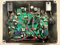
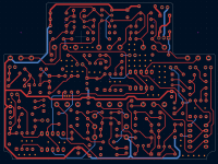
For the bypass scheme, I originally wanted to use the CMOS-based scheme I've been using for most of my recent true-bypass/relay-based builds. This uses a CD40106 (or 74HC14) hex inverter, but one bypass only requires two of the six inverters. So I thought I'd get some space-savings by controlling all three footswitches with a single hex inverter. But the the trace routing was an absolute mess. So I reverted to one of my earliest relay bypass designs, based on a microcontroller. This is the simple version, where the microcontroller directly drives the relay. It's a smaller footprint and has fewer supporting components compared to the hex inverter based design. And most importantly, having three distinct switching circuits directly mated to their effect made the trace routing much neater.
Overall I think the routing is reasonably neat. I managed to route the vast majority on the top layer, and only had to use one via.
I'm sending this out tomorrow, so hopefully I'll have some feedback shortly on what he thinks.
I know it's not the prettiest build, but for a prototype, I think it looks pretty good. And despite the minor cosmetic issues, given that the circuit worked perfect right away, and nothing required any rework, I'm giving myself five stars.
Although, now that I was able to pull this off, he's already asking about shrinking it down to fit in a 125B!")
We went back and forth for a while, brainstorming ideas. He had a rough idea of what he wanted, but a lot of our discussion was him asking how complex various circuits are, and did I think I could fit them all in a relatively compact enclosure. So naturally we had to lean towards simple circuits, just due to available PCB space. What we ended up with is the following, in order from input to output:
- Always-present buffer (I used a Cornish buffer, see PedalPCB C-Buffer). This was my suggestion, as my thinking was a low-impedance signal might be more noise resistant, and also, even with all three circuits bypassed, there's quite a bid of implicitly added "cable length". I also admit to a pro-buffer bias.
- Naga Viper (PedalPCB Dragon's Breath Boost, my personal build). To save a potentiometer, I hard-wired the "heat" control to be at max. I also added some jumpers to the end of the circuit so we could experiment with low-pass filters to tame some the high-end, as he really wanted more of a mid-boost rather than a pure treble booster. I played around with values by ear, and am including several components both bigger and smaller so he can tune to his ear/guitar/amp.
- Scarab Deluxe (PedalPCB Dung Beetle, my original build, which he bought, and the second I did for him on commission). This was always to be the "centerpiece" of the 3-in-1 design, as he loves this circuit. This circuit was implemented without any modifications.
- ZVEX Super Duper. I previously had no experience with this circuit. It's basically two series SHOs. In this design we omitted one of the SHO's master volume controls to save a potentiometer. So this circuit gets three knobs.
The prototype went together without any major issues, and worked on first power-on! The only real issue was that I drilled the holes for the status LEDs too close to the sides of the enclosure, so didn't have enough room for metal LED bezels. So I had to use some plastic ones. I also ordered a bunch of small knobs, but accidentally specified 6mm diameter instead of 6.35mm. Fortunately, I had exactly 10 of the smaller knobs you see in the pictures. But, those are about the "best" kinds of mistakes, as they don't require tedious or frustrating debugging. If you look where the DC jack comes in, it's right next to an electrolytic cap - I got lucky there, as there's only two mm or so to spare. For a "production" build I'll move the DC jack over for more "breathing room" to the cap.
For the bypass scheme, I originally wanted to use the CMOS-based scheme I've been using for most of my recent true-bypass/relay-based builds. This uses a CD40106 (or 74HC14) hex inverter, but one bypass only requires two of the six inverters. So I thought I'd get some space-savings by controlling all three footswitches with a single hex inverter. But the the trace routing was an absolute mess. So I reverted to one of my earliest relay bypass designs, based on a microcontroller. This is the simple version, where the microcontroller directly drives the relay. It's a smaller footprint and has fewer supporting components compared to the hex inverter based design. And most importantly, having three distinct switching circuits directly mated to their effect made the trace routing much neater.
Overall I think the routing is reasonably neat. I managed to route the vast majority on the top layer, and only had to use one via.
I'm sending this out tomorrow, so hopefully I'll have some feedback shortly on what he thinks.
I know it's not the prettiest build, but for a prototype, I think it looks pretty good. And despite the minor cosmetic issues, given that the circuit worked perfect right away, and nothing required any rework, I'm giving myself five stars.
Although, now that I was able to pull this off, he's already asking about shrinking it down to fit in a 125B!
")