funkmasterron
New member
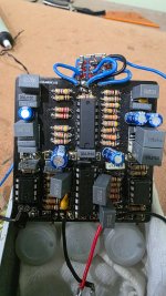
I'm working on a friend's DRD pedal that was accidently connected to 18VDC power...
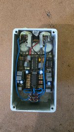
Is there a routing diagram of the PCB traces available? I'm specifically interested in how the output of IC4 (5V) net is routed from IC4 to C20, C23, and the 5V net to the other ICs.
Powering it with a Boss style 9V adapter, I see 8.82VDC going into the linear regulator IC4 (which I replaced with a 7805), but IC4 output (pin 1 closest to the PCB edge) is measuring 8.12VDC, while C20 and C23 are measuring 5.1VDC. They all should be connected together and measure around 5VDC. I have all of the other ICs removed (and replacements ready).
I'm using this document for the parts placement and schematic: