AlanH
New member
Hello guys !
I need some help here since I'm not a pro. I have a musikding Ge face kit wich was working fine but I wanted to add this inverter so I could plug it on my board without using an other power supply. Basicly I just needed -9V.
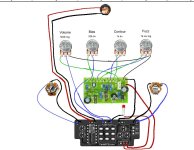
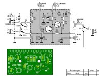
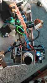
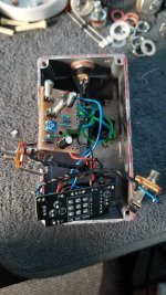
I have bypass. The switch is working fine, LED is turning on and off but when effect is "on" I have no sound. I don't know what I'm missing here. Here is the original schematics, how it was wired and what I have done so far.
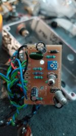
The IC was getting quite hot so I troubleshooted and resoldered Diode, Socket and capacitor around it. It's not very pretty anymore and a bit ghetto tbh but I think joints are good and nothing is shorted. (I swapped my wires on the DC jack like a dumbass but I wired it accordingly on the daughterboard. So Black on positive is "normal").
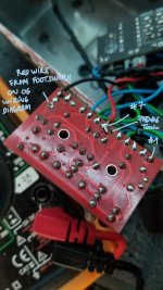
I can read +9V from the DC, on the LED but on the fixed -9V pad, I have no reading it seems... But again, the IC is socketed and everything is biping (IC lug to pad) so there is contact where it should. I'm missing something but I don't understand why !
Thank you for your help
(EDIT: wiring updated on what I did)
I need some help here since I'm not a pro. I have a musikding Ge face kit wich was working fine but I wanted to add this inverter so I could plug it on my board without using an other power supply. Basicly I just needed -9V.
I have bypass. The switch is working fine, LED is turning on and off but when effect is "on" I have no sound. I don't know what I'm missing here. Here is the original schematics, how it was wired and what I have done so far.
The IC was getting quite hot so I troubleshooted and resoldered Diode, Socket and capacitor around it. It's not very pretty anymore and a bit ghetto tbh but I think joints are good and nothing is shorted. (I swapped my wires on the DC jack like a dumbass but I wired it accordingly on the daughterboard. So Black on positive is "normal").
I can read +9V from the DC, on the LED but on the fixed -9V pad, I have no reading it seems... But again, the IC is socketed and everything is biping (IC lug to pad) so there is contact where it should. I'm missing something but I don't understand why !
Thank you for your help
(EDIT: wiring updated on what I did)
Attachments


Last edited: