DC Jacks: 2-pin vs 3-pin

I’ve been using 2-pin DC jacks. They work great and the pedals I’m building do not have a 9v battery. I’ve recently ordered some 3-prong. So, instead of simply positive and negative, it has positive, negative, and ground.

My question is… Since it doesn’t have a battery, how should I wire them up? Is it important to “ground” the ground or should I just leave it alone untouched?
 

Attachments

  • IMG_0369.jpeg
    IMG_0369.jpeg
    123 KB · Views: 5
  • IMG_0368.jpeg
    IMG_0368.jpeg
    207.7 KB · Views: 5
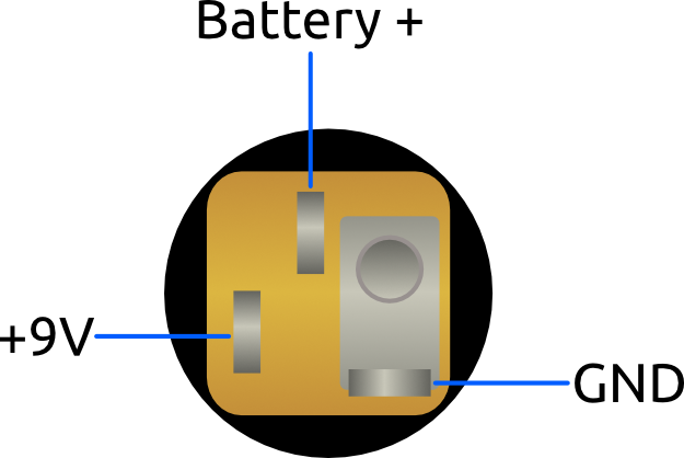
The three prong jack is a switching mechanism. When the DC barrel is inserted, it mechanically disconnects the two positivine prongs. I.e., if you have a battery's positive lead at the center prong, with no DC barrel inserted, that lead flows to the other prong and into your circuit. When the barrel is inserted that contact is broken and the 9V to your circuit is coming from the barrel.

To use these without a battery, just ignore the center prong.
 
DC_Jack_Pinout.png
 
I may be a weirdo(I am) but I usually hook both + together. I don't use batteries btw. In my head, if something goes awry with the internal switching mechanism, then it should still work. Also, I don't have to remember which is which. "2 in one direction is more, so that's positive, 1 in the other direction is different, that's negative"
It's dumb but it's how I remembered starting out. Kinda like LEDs, long leg(anode) and short leg (cathode)
The short leg is sad, it's negative.
The switching makes it so your battery is disconnected when power is plugged in. You then don't have to unplug your input cable to keep the battery disconnected. Since you don't use a battery, what do you mean by "both +", you install the connector but don't put a battery in ?
 
Ok, cool. This makes sense, but not what I expected based on this diagram image of the item I purchased (below). I thought it was negative, positive, ground based on the diagram (below). My guess is it just depends if the circuit calls for a negative or positive pin tip from the DC jack but I don’t know.
 

Attachments

  • IMG_0379.png
    IMG_0379.png
    369 KB · Views: 6
The switching makes it so your battery is disconnected when power is plugged in. You then don't have to unplug your input cable to keep the battery disconnected. Since you don't use a battery, what do you mean by "both +", you install the connector but don't put a battery in ?
When soldering the red/+ wire to the jack, I'll strip a little extra and run it through both the + and battery terminal. Then solder both points. Basically defeating the internal switch and turning it into a 2 terminal
 
Back
Top