TheCrookedMan
Member
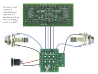
I'm finishing up my Deflector build and I'm trying to use a Fuzz Dog Optopuss bypass that I have lying around, but I'm a little confused about how to wire it. Here's what I'm trying to find out:
- Based on the Optopuss documentation, I definitely have to use the power and LED connections on the daughterboard instead of the main board, but do I just leave the main board's connections empty?
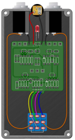
- For the connections between the main board and daughterboard, CI goes to IN, G goes to GND, and CO goes to OUT, but what does SW on the main board mean? It seems obvious that it'd go to V, but I just want to make 100% sure, especially since none of those connections are labeled on the main board and the wiring diagram seems to be for a random pedal, not the Deflector specifically.


