Double Mosfet boost with send/return loop + remote

jezkemp

New member
Hi there, long-term reader, first-time poster here. Hoping to get a bit more involved on here.

Here's a project from the summer, hope it's okay to share own builds as well as PPCB builds.

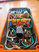
Double mosfet boost (SHO) with send and return, so you can boost gain and volume of your favourite OD pedal or amp channel at the same time. Uses relays so they can both switch instantly on a single kickswitch, and can be controlled by a remote footswitch or channel switching gear.

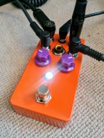
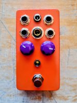
The "be not afraid" layout has all sockets on the top, to save horizontal space on small pedal boards where space is a premium.

It's currently with a mate whose initial feedback is quite positive. When I get it back I want to add a simple decal and call it done. Overall I'm happy this works and does what it should.

Bugbears and next steps for me:

  • The sockets spacing is slightly off and it bugs me. My stepper drill bit likes to run around, so I used a 2mm bit which was even more slippery. Lol, lmao
  • The "pop" on the kickswitch is fairly chunky, even with pulldown resistors and flyback diodes. I'm looking into optocouplers / photo mosfets for taming it a bit on future projects.
  • Putting all the jacks on top is absolutely a gimmick and I'm enjoying it, but a downside is not being able to use an angled cable for the remote jack. All useful data for future projects.
  • The less said about the soldering the better!
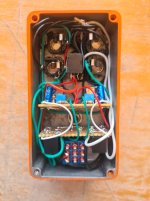
  • The relay bricks are frankly too big for their own good. Their board is held in by the LED – defo not structurally sound, again useful data for future projects.
 

Attachments

  • 20260614_180607~2.jpg
    20260614_180607~2.jpg
    299.3 KB · Views: 26
  • 20260614_180617.jpg
    20260614_180617.jpg
    316.6 KB · Views: 25
  • 20260614_180508~2.jpg
    20260614_180508~2.jpg
    354 KB · Views: 26
  • 20260614_175942~2.jpg
    20260614_175942~2.jpg
    382.3 KB · Views: 23
That’s really cool! Definitely the first build I’ve seen here with jacks on the front face. Kinda gives it the look of a cable snake or patch bay.

As for your step bit wandering: are you drilling pilot holes? I stubbornly refused to drill pilot holes when I first started building, and was always disappointed when my holes weren’t well aligned. Once I started using the pilot holes, I immediately regretted not using them previously. I actually first use a center-punch type thing to make a small dent at the center of all the holes. That helps the small pilot bit stay in place.

If you post a schematic of the relay switching scheme you’re using, we can take a look and see if there’s anything obvious that might be causing the popping.
 
Hi there, long-term reader, first-time poster here. Hoping to get a bit more involved on here.

Here's a project from the summer, hope it's okay to share own builds as well as PPCB builds.

Double mosfet boost (SHO) with send and return, so you can boost gain and volume of your favourite OD pedal or amp channel at the same time. Uses relays so they can both switch instantly on a single kickswitch, and can be controlled by a remote footswitch or channel switching gear.

The "be not afraid" layout has all sockets on the top, to save horizontal space on small pedal boards where space is a premium.

It's currently with a mate whose initial feedback is quite positive. When I get it back I want to add a simple decal and call it done. Overall I'm happy this works and does what it should.

Bugbears and next steps for me:

  • The sockets spacing is slightly off and it bugs me. My stepper drill bit likes to run around, so I used a 2mm bit which was even more slippery. Lol, lmao
  • The "pop" on the kickswitch is fairly chunky, even with pulldown resistors and flyback diodes. I'm looking into optocouplers / photo mosfets for taming it a bit on future projects.
  • Putting all the jacks on top is absolutely a gimmick and I'm enjoying it, but a downside is not being able to use an angled cable for the remote jack. All useful data for future projects.
  • The less said about the soldering the better!
  • The relay bricks are frankly too big for their own good. Their board is held in by the LED – defo not structurally sound, again useful data for future projects.
very cool . I'm looking at doing something like this, except using some microamp boards
 
That’s really cool! Definitely the first build I’ve seen here with jacks on the front face. Kinda gives it the look of a cable snake or patch bay.

As for your step bit wandering: are you drilling pilot holes? I stubbornly refused to drill pilot holes when I first started building, and was always disappointed when my holes weren’t well aligned. Once I started using the pilot holes, I immediately regretted not using them previously. I actually first use a center-punch type thing to make a small dent at the center of all the holes. That helps the small pilot bit stay in place.

If you post a schematic of the relay switching scheme you’re using, we can take a look and see if there’s anything obvious that might be causing the popping.
Hey! So with the relays, there's no schematic, it's literally just 2x 9V relays plugged into the raw 9V DC and doing classic true bypass.

Since making this I've already realised a couple of things like grounding the inputs which might help*, also there's no power filtering on these boosts, so maybe that might help.
*Edit- just remembered I did this!

I know a lot of relay bypass kits/modules use a regulator to create 5V, I always assumed that's just because of a) microcontrollers run on 5V, and/or b) 5V relays are much more widespread than 9V relays. But I'm wondering if there's *maybe* a chance 5V creates less pop than 9V.

Re: wandering drills, can you believe I double-punched the holes on this lol. I already knew my cheap stepper bit likes to wander around, so I used a dedicated 2mm bit, which was even worse. I've since found a better 2mm bit – fingers crossed for the next build!
 
Last edited:
Back
Top