- Build Rating
- 5.00 star(s)
Here's a complete do-over of my "Dynamic Haircut", which is a clone of the Barber Gain Changer. Here's the build report for v1.0, which I did almost four years ago. I sold that build a while ago. I had long since given away my last v1 PCB, and someone recently messaged me asking if I had any left. That got me thinking about this circuit, and eventually I decided it was time to revisit it.
Funnily enough, the PCBs for v2.0 were delivered while I was working on the PedalPCB Sliver (Barber LTD SR). That motivated me to quickly build the Dynamic Haircut so I could compare them side-by-side.
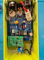
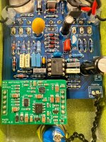
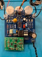
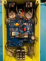
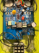
You can see the big, mostly-empty space at the bottom of the PCB. That's space for my still-in-the-works Buffer + Bypass "Quasi-IC" Module. The mechanical 3PDT switch is a temporary stop-gap until the module is ready for use. The same JLCPCB order that included this PCB also included an (assembled) SMD PCB that is essentially a sub-set of the quasi-IC module (but for a different purpose). Unfortunately, that doesn't work, and in fact started smoking not too long after I applied power, so I've got some debugging work ahead of me - the quasi-IC might not be ready as soon as I'd like!
Anyway, this is a great, highly recommended circuit for a fairly transparent, well-tuned light overdrive. The higher-gain Unlimited side gets into pretty decent mid-gain drive as well. I'm a big fan of the user interface: three knobs and two switches gives a lot of flexibility and tweaking capability, but at the same doesn't feel overwhelming, or feel like there are more knobs than necessary.
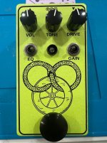
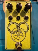
The enclosure is the April, 2026 limited edition finish from Love My Switches. It looks sorta yellow in this picture, but it's actually more like a lime green. The graphic is from Robert Jordan's Wheel of Time fantasy epic. I recently read all 14 books and the prequel.
I have a few PCBs available if anyone wants one, just PM me.[/i]
Edit: see post #3 below for an update to this build.
Funnily enough, the PCBs for v2.0 were delivered while I was working on the PedalPCB Sliver (Barber LTD SR). That motivated me to quickly build the Dynamic Haircut so I could compare them side-by-side.
You can see the big, mostly-empty space at the bottom of the PCB. That's space for my still-in-the-works Buffer + Bypass "Quasi-IC" Module. The mechanical 3PDT switch is a temporary stop-gap until the module is ready for use. The same JLCPCB order that included this PCB also included an (assembled) SMD PCB that is essentially a sub-set of the quasi-IC module (but for a different purpose). Unfortunately, that doesn't work, and in fact started smoking not too long after I applied power, so I've got some debugging work ahead of me - the quasi-IC might not be ready as soon as I'd like!
Anyway, this is a great, highly recommended circuit for a fairly transparent, well-tuned light overdrive. The higher-gain Unlimited side gets into pretty decent mid-gain drive as well. I'm a big fan of the user interface: three knobs and two switches gives a lot of flexibility and tweaking capability, but at the same doesn't feel overwhelming, or feel like there are more knobs than necessary.
The enclosure is the April, 2026 limited edition finish from Love My Switches. It looks sorta yellow in this picture, but it's actually more like a lime green. The graphic is from Robert Jordan's Wheel of Time fantasy epic. I recently read all 14 books and the prequel.
I have a few PCBs available if anyone wants one, just PM me.[/i]
Edit: see post #3 below for an update to this build.
Attachments
Last edited: