EHX Germanium 4

Chuck D. Bones

Circuit Wizard
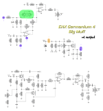
Anyone have one of these? One of the members DM'ed me asking about it, so I did a little research. If the schematics on FSB are to be believed, and I think they are at least 90% correct, the two halves are nothing like a BMP. Looks to me like EHX is trading on the MUFF name in order to boost sales.

Anyway, the Distortion side of the pedal is basically a Distortion + with a voltage sag and a booster at the end. I suspect an error in the booster gain setting resistors (R7 / R8) because with the values shown, the booster overdrives before the diodes do any clipping. The Ge clipping diodes are a pair of Ge transistors. The BIAS knob controls how hard the opamp hits the diodes.

EHX Germanium 4 Muff - distortion side 2022-10-22.png

It's hard to tell from the trace schematic, but the OD side is essentially the 2nd stage of a Tube Bender driving a pair of opamps. Here too, the opamps do most of the clipping unless the BIAS is dialed way down. The schematic identifies the transistors as PN2222A, which are neither PNP nor Germanium, so I think the part number is a typo. My experience using Ge transistors in a Tube Bender tells me that there is very little tonal difference between Ge & Si when used that way. I might try breadboarding the OD side, but right now I'm, playing with two other Ge dirt pedals: The Germanium Fuzzrite & the Roger Mayer Page-1. Those two will appear in the near future in The Boneyard.


EHX BMP Germ4 OD side.jpg

Here's a better (easier to read) schematic of the OD side. It does not include the TONE network at the end.

1742524970612.png
 
Last edited:
I got one for cheap because it was partially broken. I believe the transistors are NKT 275's? The OD side specifically had a buzz and was acting wonky, I replaced them with some random soviet GE transistors I had and it works like a dream now. I think the faulty ones tested as diodes on mine, or at least one of them, and the other had single digit hfe.

Here are some pics too
FWIW I think the OD side is... ok. The Distortion side is much more interesting to me with the volts control. I got a cool guitar tone almost reminding me of Master Boot Record with it.
 
I might have to breadboard it. On paper, it's unimpressive... basically over-driven TL072s on both sides.

On the Distortion side, where do you like to set the GAIN & BIAS knobs?

When you say "I believe the transistors are NKT 275's" how are (were) they marked? Which transistors did you replace? The ones on the Distortion side or the OD side? The ones on the Distortion side are wired as diodes, so they could be pretty f'ed up and still work in that circuit.
 
I might have to breadboard it. On paper, it's unimpressive... basically over-driven TL072s on both sides.

On the Distortion side, where do you like to set the GAIN & BIAS knobs?

For a more conventional distortion, I'd set the gain to ~9-10'o clock and Bias to full, with quite hot humbuckers and amp. But I'd guess the Bias depends on how your guitar and amp are set up too, since it's the closest to a tone control you get on the Distortion side. Obviously it's not a tone control, but turning the Bias down makes it darker.

For the "floppy disk drive run through a distortion" type sound I set the Volts quite low (like 3'o clock), Gain ~full (it doesn't really matter too much, but it gets very choked so more is more - I still need to run it into the OD side to get a decent volume out of it) and Bias maybe halfway down. Bias doesn't seem to make a huge difference to the sound here otherwise, but you can control how much it gates, so around half it gates out most of the noise works well for playing. That being said, it's definitely in the family of "really fun to play with, now if I could just figure out what to do with it", kinda like the Unpleasant Surprise and such.

That sound mostly stood out to me because it's the most remarkable thing about the pedal, to me. Otherwise it feels more like "Hey imagine a standard distortion and overdrive, but they're both in one box, exciting right?".

When you say "I believe the transistors are NKT 275's" how are (were) they marked? Which transistors did you replace? The ones on the Distortion side or the OD side? The ones on the Distortion side are wired as diodes, so they could be pretty f'ed up and still work in that circuit.
DSC_3876.JPG DSC_3875.JPG DSC_3874.JPG
Not sure what that logo is, looks like a D with wavy stuff in the middle. The other two were marked similarly IIRC (like I said, I threw them away).

I replaced the ones on the OD side, because the OD side had issues. The Distortion side was fine so I didn't touch it (and yeah I also read they were used as diodes so wouldn't cause the kind of issues I had anyway).

The redditor who posted pics of their pedal seems to have slightly different markings on theirs , and they look bulkier than mine too. Not sure if they're all genuine, from googling my issue with the pedal before it seems that they are prone to the OD side hissing/gain issue, similar to what I had, so maybe you could read into that.

FWIW I also heard complaints that the OD side can be too bright for some, but not others, so could be transistor variance there too? I like how the ones I put in sound, I feel like it maybe has slightly more gain than a stock version too, but I can't be sure since mine was broken when I got it.
 
Hi guys, I'm trying to trace this circuit. Has anyone assembled this pedal?

I have a couple of questions about the diagram:

IMG_3328.png IMG_3329.png Schematic-EHX-Germanium-Muff-2022-10-22.png BMP Germ4 Dist.png


*in the photo of the original board, there is a C18 capacitor (10nF) - the power goes THROUGH it. Is it needed in the diagram? I have never seen such a thing in any pedals. Would you recommend leaving it or replacing it with a jumper?

*VOLTS potentiometer - regulates voltage on pin 8 of the microcircuit (distortion section)?

*the most interesting thing is the TRANSISTORS.

In the diagram, they are connected together with the CB. the E is free (as a diode).
Which side are they connected to in the diagram?
- in series
- in parallel
- symmetrical
- asymmetrical

*is there a capacitor C4 (20u) in the photo of the original board...
 

Attachments

  • germanium4_5555.png
    germanium4_5555.png
    439.7 KB · Views: 9
Last edited:
The UNVERIFIED Distortion side schematic clearly has errors.

1. The correct connection for Q1 & Q2 is parallel, not series. They are wired as hard clipping diodes. Why EHX used transistors instead of diodes is anyone's guess.

2. If C18 was wired as drawn, then the pedal would not work because capacitors block DC.

The photos don't tell the whole story because there can be connections which are not visible.

I believe that the 1st & 3rd schematics at the top of this post are correct. Have you tried breadboarding it? IMHO, there is nothing remarkable about this pedal.
 
While it is possible, I don't believe that Q3 & Q4 are PN2222A Si NPN transistors because
1. NPN is the wrong polarity.
2. Q3 & Q4 are metal can transistors marked NKT275 in the photos. PN2222A are TO-92 plastic transistors.

How many of these do you intend to make?
 
You're right, I didn't pay attention to that, I just copied the values from the schematic.

Most likely, the overdrive section is also an NKT275. Photos of the original boards show transistors marked NKT (and there's silkscreen printing nearby, too).


undefined - Imgur.png BMP Germ4 OD.png EHX-Ge4BMP-OD.png
 
Back
Top