Right, apologies for the delay, Christmas and New Year rather got in the way and by the time that was over, I'd forgotten what exactly I'd done so needed to open it back up again!
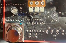
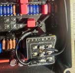
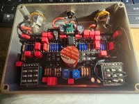
First off, let me note that the pedal in the original post was a Christmas present for my brother and I didn't get any gut shots because I was in such a rush getting it done. I therefore have gut shots from the prototype as it were, the version I made for myself first which was nearly finished before I decided to modify it, so it's not the best workmanship.
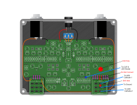
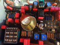
Excuses out of the way, see the below graphic which explains what I have done. Firstly you need to drill a couple of holes in the pcb, one rather large on where the LED pads are for the speed LED, and one on the footswitch board if you're using that. Please be careful you do not sever important traces, check it very carefully. The large hole on the main pcb is simply to make space for an LED to pass clearly through and be wired point to point above the board. The hole on the switch board is to sever a trace and allow one of the poles to be repurposed.
Following this you will need to wire an off board current limiting resistor to the LFO output. This can be taken from a number of places, I selected the upper pin of R19. The other end of the resistor will connect to the anode of a common anode dual or triple LED. I used triple because it had the colour combination I wanted, so I just snipped off the cathode for the colour I didn't want to use. You will then connect each cathode to the footswitch board, upper and lower pads of the middle pole. Final job is to connect the middle pad of that pole to ground, of which there are many places to choose from. Ideally pick a ground that is close to the 9V jack and not in the signal path.
Final thing to point out is that the central 2 pads on the footswitch-to-main board should not be connected, I've coloured these red.
Here's this information in visual form, I'll follow up with some actual gut shots.