First Breadboarding Attempt and... Nothing

andrew

New member
Hello!

I've recently made my first breadboarding attempt (with the Uberfuzz — maybe a bit ambitious for a first time but I'm hoping to test a few component swaps). I've built it out, tested it, got zero signal, tore it out, and rebuilt it. Still no signal.

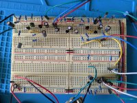
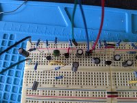
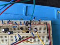
I'm preeeeetty confident in the circuit (like, maybe 80%). So I'm not looking for a diagnosis, though I'm attaching pictures because I know somebody's gonna ask for them.

What I'm wondering is: are there any sort of basic things that trip beginners up, "common sense" stuff that they just don't know about? For example: do I have to ground it somehow other than to the negative of the power supply? Do I have to connect the power circuit to the main circuit in a particular way (as opposed to just through the power/ground rails)? Are there certain schematic symbols that are commonly misread by new users?

I can't shake the feeling that my issue is a big, dumb, in-your-face one, as opposed to a particular connection somewhere.
 

Attachments

  • full view.jpg
    full view.jpg
    354.3 KB · Views: 7
  • top left-input.jpg
    top left-input.jpg
    270.6 KB · Views: 8
  • top right.jpg
    top right.jpg
    207.6 KB · Views: 6
  • bottom right-output.jpg
    bottom right-output.jpg
    400.7 KB · Views: 8
Last edited:
Hi Andrew,

Your power rails look correct. 8 times out of 10 I've missed a node hole by one. Do you have an audio probe? You can trace the signal by touching the leads. With a BB, you can even just shove a wire into an open output hole, and touch the other end along the signal path.
 
It's easy to pop a transistor in back to front, and you can also get some that have a different leg order, like a BC183 and a BC183L! So google a data sheet for your specific transistors and check you are putting them in the right way.

Bread boards can be a pain as sometime you just don't get a good connection and start chasing your tail looking for an intermittent fault.

As a quick 'lets see where we loose signal' process you can split schematic into several blocks so temporarily connect the output to pin 2 of the expander pot and see if there is a signal (if you have a looper pedal record a little something and keep that looping into the input also keep your amp level low the signal level may jump around a bit as you probe different parts of the circuit), if not, look for a fault in everything leading up to there. If you have a signal move on and see if you have a signal between C10 and C11.

Then pin 2 of the balance pot.
 
Last edited:
It's easy to pop a transistor in back to front.
I was very careful about this but will definitely double check.
As a quick 'lets see where we loose signal' process you can split schematic into several blocks so temporarily connect the output to pin 2 of the expander pot and see if there is a signal (if you have a looper pedal record a little something and keep that looping into the input also keep your amp level low the signal level may jump around a bit as you probe different parts of the circuit), if not, look for a fault in everything leading up to there. If you have a signal move on and see if you have a signal between C10 and C11.

Then pin 2 of the balance pot.
So, basically an audio-probe-for-people-with-no-audio-probes. Very clever, not sure I ever would've thought of that.

The points that you picked in your example: is there something special about them, or are they just easily identifiable spots?
 
I chose places after a coupling capacitors, or in the case of pin 2 of the balance pot before the coupling capacitor, these capacitors block direct current from moving from one part of the circuit to the next, but they allow your guitar signal through which is an alternating current. This means when you take the output from those places you are only getting the audio signal.

If you have a multimeter set it to DC voltage and connect the black lead to a ground on your circuit, now probe one side of C6 and then the other side and you should have a 3.5v or there about on the + side of the capacitor and 0 on the other.
 
Nope, but I've been meaning to DIY one with an old instrument cable — guess I've got my excuse to finally do it!
You can save the cable if you have alligator clips. Plug the cable to your amp into a spare jack, one clip to ground on BB and jack, another clip to the signal part of the jack and the other end of that wire to a 100nf capacitor. The spare lead of the capacitor is your audio probe. Its messy but it works.
 
I chose places after a coupling capacitors... these capacitors block direct current from moving from one part of the circuit to the next, but they allow your guitar signal through which is an alternating current.
excellent to know, thank you
If you have a multimeter set it to DC voltage and connect the black lead to a ground on your circuit, now probe one side of C6 and then the other side and you should have a 3.5v or there about on the + side of the capacitor and 0 on the other.
I've checked this a few times since you suggested it. The numbers jumped around a bit but seem to have settled at about 3-4 mV on the - side, about 4V on the + side. So pretty good! (I didn't notice that I was getting an mV measurement the first time and was very confused.)

Regarding probing, I had signal all the way up to the 2nd lead of R1 🙃
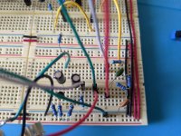
. I've tried two different resistors here, same result with both (ohm tested both with the multimeter and they both checked out). So I'm pretty flummoxed about that.
 
Back
Top