Fornicus Sag Cutoff

ThomasAvenue

Active member
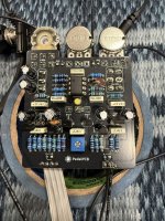
Checked other Fornicus troubleshooting threads but from what I read those issues presented a little differently. When the Sag switch is engaged and the threshold is barely adjusted CW the entire signal gets swallowed up and cuts off. Totally unusable and not like demo videos.

Yellow LED is ~1.8V
FSW Red LED is ~1.5V
Momentary FSW Red LED is ~1.8V

IMG_9707.jpeg

 
Maybe not, but I got them from Tayda many years ago…?

I would’ve thought not but the Obsidious Preamp I just built uses two J201s and it’s also having strange choked signal issues that I can’t find a glaring fault for.
Ding Ding.... I'd suggest getting some smt ones on daughterboards... you'll generally have better luck with J201's that way....
 
For the Obsidious I would socket the JFETs as well, if I remember correctly they are in a mu configuration so they need to be arranged in a specific way. I would read up on JFET configurations to get some more context on this.
 
Last edited:
Ordered some MMBFJ201 from Aion. I’d be thrilled if it was just some fake J201s plaguing a few builds. I do clean builds so I trust my work but I’m not initiated in vetting parts, so if something goes wrong that isn’t a mechanical or connective issue I get lost pretty quick on where to look.
 
Ordered some MMBFJ201 from Aion. I’d be thrilled if it was just some fake J201s plaguing a few builds. I do clean builds so I trust my work but I’m not initiated in vetting parts, so if something goes wrong that isn’t a mechanical or connective issue I get lost pretty quick on where to look.
PM me if your in the states.... I can drop you 4or 5 legit through hole ones ones in the mail.... I have a small stash of through hole ones that are legit. Since you already have sip sockets soldered in you can swap through them and see if it acts right with some verified ones.
 
Installed the MMBFJ201 in my build and I’m not really sure it made much of a difference, so perhaps my J201s aren’t fake or they have a different bias point, so how it presents when playing with the trimmer is just shifted to a different spot in the travel…?

Double checked my values and they’re all correct. The weight switch is making no discernible aural difference whatsoever, so I’m confused with this build. By all metrics I’ve assessed so far it’s built and spec’d correctly but its behavior is wrong/incomplete/lacking.

I’m also working on a Lilliput that is not dissimilar in that even with MMBFJ201 installed the bias isn’t acting how I recall it working on an actual Mini.

It’s beyond my current level of skill to diagnose what could be amiss when all that was prescribed and spec’d is accurate with no build issues and, ostensibly, reasonably accurate biasing…?
 
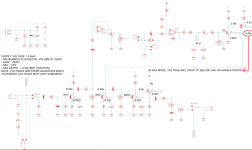
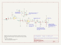
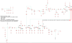
Judging by the pictures and the original demo, your J201 stages seem to be fine (I hear the gain and clipping), what is the drain of Q2 (2N5457) measuring? I suspect the problem is between IC1.1 and Q5 2N5089 on the PPCB schem which is the envelop follower/sag section
 
Looks like 4.08V
1794357869743.png 1794357907070.png
That seems right from my experience, 4-6V seems to work there, DEFX also has Q2 at around 4.5V
I don't think anything is actually wrong with the drive section or your JFET selection
Hmmm... check Q5 (2N5089) pads against the DEFX measurements and maybe try swap out the TL072 for a different one, the problem might be (in my opinion) in the envelop follower section controlling the sag of Q2
 

Attachments

  • 1794357658984.png
    1794357658984.png
    342.2 KB · Views: 6
View attachment 127575View attachment 127576
That seems right from my experience, 4-6V seems to work there, DEFX also has Q2 at around 4.5V
I don't think anything is actually wrong with the drive section or your JFET selection
Hmmm... check Q5 (2N5089) pads against the DEFX measurements and maybe try swap out the TL072 for a different one, the problem might be (in my opinion) in the envelop follower section controlling the sag of Q2
I'll check as soon as I can get back to my shop!
 
View attachment 127575View attachment 127576
That seems right from my experience, 4-6V seems to work there, DEFX also has Q2 at around 4.5V
I don't think anything is actually wrong with the drive section or your JFET selection
Hmmm... check Q5 (2N5089) pads against the DEFX measurements and maybe try swap out the TL072 for a different one, the problem might be (in my opinion) in the envelop follower section controlling the sag of Q2
Q1 7.34, .165, 0
Q2 4.08, .82, 0
Q3 5.77, .21, 0
Q4 5.15, 5.77, 8.99
Q5 0, .002, 4.8
Q6 4.1, 4.08, 4.81
 
Back
Top