Grover drive question.

Crispy

Member
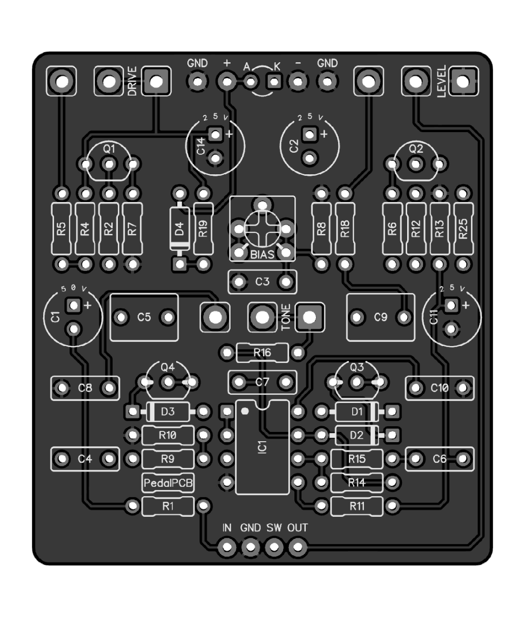
Ive been wondering,do you think it would be worth my effort to add the missing 4 pots with jumpers in place of the resistors , two foot switches for each circuit and try to make this Grover Drive PCB a love pedal silicon Fuzz master/ Zen Drive 2n1? i was thinking on the Zendrive side change R11(220k) to a 500k gain pot R12(4k7) to a 10k Voice pot . the Fuzz side change R1(33k) with a 100k blend pot C2 (100nf) to 4n7 and replace R8R18/R9R19 voltage divider with a 250k volume pot . or should i just build my Grover Drive PCB stock and start another project with my idea?
 
I thought about doing this with an order switch, because the opposite order is supposedly the 200lbs of gold pedal he makes. I haven't seen the 200lbs of gold schematic to verify so I don't know if any other tweaks happened. I think if you have any intention to use them separately it would be worth your effort, you could even mark on the enclosure where the "factory" settings are.
 
the more i look at it i think it would be kinda easy to pull off. i think the important part would be making sure i have marks on each of the extra pots showing me the stock value to run it in Dover drive mode. i was not even considering an order toggle . now that you mention it i wonder what it would sound like.it would just be one extra 3pdt toggle switch ive got a bunch of those on hand i might as well add that too. it should fit in a 1590bb i hope. im going to give it my best shot i hope i dont mess it all up LOL.
 
I just ordered this with my latest PCB order, um, because I'm a sucker for a "sale item" and it was only $4:)

What's the difference between the Grover and a Zen?
 
I just ordered this with my latest PCB order, um, because I'm a sucker for a "sale item" and it was only $4:)

What's the difference between the Grover and a Zen?
that has me thinking of getting a couple more just to have on hand ready to build at that price . as far as i can tell other than the fuzz circuit on the input, starting at the first 470nf cap it seems to be the same as a Zen drive with the voice and gain nob set to around 50% with a resistor vs the normal pot. the fuzz circuit looks a lot like Lovepedals Fuzz Master, with what looks like the volume nob replaced with a voltage divider to better match the fuzz circuit output to the ZenDrive input.
 
that has me thinking of getting a couple more just to have on hand ready to build at that price . as far as i can tell other than the fuzz circuit on the input, starting at the first 470nf cap it seems to be the same as a Zen drive with the voice and gain nob set to around 50% with a resistor vs the normal pot. the fuzz circuit looks a lot like Lovepedals Fuzz Master, with what looks like the volume nob replaced with a voltage divider to better match the fuzz circuit output to the ZenDrive input.
I just went and watched some demo's of this pedal. What was a passing curiosity in a marked down board is turning into a serious interest now hahah. I'm thinking about putting the Bias trimmer on a pot and exposing it. That way I can dial between a more Zen like overdrive or more fuzzy drive on the fly.
 
I may add another toggle for C2 so i can change between 4n7 like the Fuzz Master and the 100nf the Dover driver uses . so far ive split the two circuits Fuzz Master / ZenDrive added the missing pots inplace of the resistors the DD uses ,made them both true bypass and added a order toggle so i can see what it sounds like to run a Zen Drive into a Fuzz Master
1661534614780.png 1661534638784.png 1661534659353.png
 
I thought about doing this with an order switch, because the opposite order is supposedly the 200lbs of gold pedal he makes.

I'm not sure how the confusion happened but they're basically the same circuit aside from the 100nF cap on the input. The order is the same, although it will be interesting to hear them with the order swapped.

Some folks have mentioned oscillation at higher gain settings with the Grover, removing the 100nF seemed to remedy that.
so like an opposite order dover drive?
Ahhh you know, you're right. I didn't even catch that.

There's a couple components different but that's basically what it is.

Someone said it was zen>ff and then when you said you're right I thought it was in response to one of us so I thought it was an opposite order dover confirmed, just a misunderstanding it seems.
 
Some folks have mentioned oscillation at higher gain settings with the Grover, removing the 100nF seemed to remedy that.
Yup, mine definitely does that at the extreme end of the gain range, but I'm talking 3-4 o'clock.
Won't bother me since I'll never run the gain that high.
 
Some folks have mentioned oscillation at higher gain settings with the Grover, removing the 100nF seemed to remedy that.

I can see how that would happen, depending on what you're using to drive the Grover. C2 is only appropriate when driving with a high-impedance source, like a guitar. Driving the Grover with another pedal, especially one with a low output impedance, will drive the Grover bat-shit. I'd ditch C2.
 
I removed C2, wow big difference. I thought it was just a noisy pedal but with the headphones on the "noise" was actually oscillation that increased when you dial the gain up. Taking out the 100nf input cap as @PedalPCB and @Chuck D. Bones suggested makes it whisper quiet all the way through the gain range. @Crispy highly recommend you leave it out.
 
Very clean build. Wire routing is impeccable.

Three questions:
1. How is the board supported?
2. Are those transistor bodies touching?
3. You changed Q1 & Q2 from Si to Ge. This will alter the biasing. How to you plan to deal with that?
 
That's an interesting question. I just had a look at the Grover schematic and don't quite understand it - no surprise there! I didn't know you could use PNP transistors like that. To my ignorant eye it would seem that the bias is controlled by the trim pot, the gain pot and R2. R4 plays a role obviously but as it's connected to the trimpot I would have thought that was negligible. Do I have this wrong? And sorry for jumping into someone else's thread! I'm interested in how this works.
 
Yes, you can build a FF "upside-down." That way you don't need a -9V rail to power a PNP circuit. You guys in Oz live in an upside-down world, so it should seem natural to you ;).
Kidding aside, the first stage is a FF with the GAIN control implemented in a slightly different fashion.
Yes, the GAIN control & Bias trimpot can adjust the bias, but it's unclear whether they have sufficient range to accommodate the switch from Si to Ge. Crispy will find out. Turning the bias trim changes the bias on Q2 and the signal level going to IC1.1. Crispy might need to adjust R2.
 
That's an interesting question. I just had a look at the Grover schematic and don't quite understand it - no surprise there! I didn't know you could use PNP transistors like that. To my ignorant eye it would seem that the bias is controlled by the trim pot, the gain pot and R2. R4 plays a role obviously but as it's connected to the trimpot I would have thought that was negligible. Do I have this wrong? And sorry for jumping into someone else's thread! I'm interested in how this works.
I removed the 100nf Input cap from the Grover but there is still another 100nF cap amiss in that circuit I believe! o_O
Check out the 5lb Bag Fuzz, it's basically the same circuit, just 180 degrees!
I've built both and prefer the 5lb Bag any day!
 
Back
Top