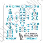
Heavy Metal Megalithic King footswitch wiring

Putrid Electronics

Active member
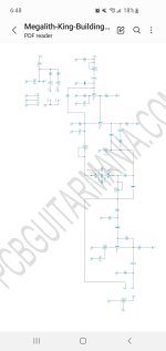
Just need helpnwith footswitch for the MORE function. Signal path is split to two paths. P2 is with the Q3 transistor in the path, P3 bypasses the Q3 transistor. P1 is the output of two paths. I am assuming I will need to wire pin 1 to P2 pad, P3 pad to pin 3, P1 pad to Pin 8, and then standard LED wiring? I have it currently wired P1 to Pin 2, P2 to Pin 1 and P3 to Pin 3. And LED works no issue. Only issue I am running into is no signal on the normal setting. The MORE setting functions as it should


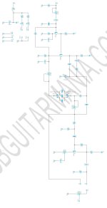
Screenshot_20261017-184900_Samsung Notes.jpg Screenshot_20261017_184917.jpg
 

Attachments

  • Screenshot_20261017-184900_Samsung Notes.jpg
    Screenshot_20261017-184900_Samsung Notes.jpg
    98.7 KB · Views: 2
Last edited:
Pin numbers on schematic match to lugs in spdt switch. P2 is the middle lug.

With LED indication you’d need a dpdt switch
They included a standard footswitch PCB AND a 3pdt auxiliary pcb for a footswitch as well. So I have to assume that LED is wired standard way. I have everything working as it should except for the signal path bypassing the last transistor. Sounds like I just have
2 in the wrong pads
 
Last edited:
Back
Top