burger-patty-and-bacon
Active member
I have never used a breadboard in my life. I built one with a power jack, the io jacks and a mini toggle. I am feeding this with a 9V one spot. For fun, I simply wanted to light up an LED but will eventually use this to test pedals and maybe "design" stuff. I am a total newbie, I know enough to be dangerous.
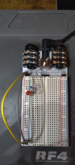
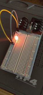
Here is a pic of my experiment. I have the left side VCC to + of ROW 30 and the GND to - of ROW 30.
In ROW 8 I have the + of a red LED in the + of the power reail and the - of the LED in ROW 8 "a".
Then I have a 2.2k resistor in - of "power rail" and the other part in row 8 c.
what I am doing totally wrong here?
 . A shameless self-plug, I know, but I'm excited for you learning how to breadboard! If you want a different circuit that isn't there just message me and I'll help out. I've got some time during the days this week.